Thermodynamics

DOE Fundamentals Handbook - Thermodynamics, Heat Transfer, and Fluid Flow $13.95
The Thermodynamics, Heat Transfer, and Fluid Flowhandbook explains all you need to know about Thermodynamics and the three modes of heat transfer: conduction, convection and radiation. If you plan to do any solar heating experiments, or just want to understand and improve your home’s heating systems, this book will prove INVALUABLE. The handbook also describes the properties of fluids, the relationship between the different types of energy in a fluid stream through the use of Bernoulli's equation and discusses the causes of head loss in fluid systems and the factors that affect head loss. This book will provide you with the basic understanding of Thermodynamics, Heat Transfer and Fluid Flow needed to be part of the hydrogen revolution.
DOE FUNDAMENTALS HANDBOOK THERMODYNAMICS, HEAT TRANSFER,AND FLUID FLOW
VOLUMES 1-3
The Department of Energy (DOE) Fundamentals Handbooks consist of ten academic subjects, which include Mathematics; Classical Physics; Thermodynamics, Heat Transfer, and Fluid Flow; Instrumentation and Control; Electrical Science; Material Science; Mechanical Science; Chemistry; Engineering Symbology, Prints, and Drawings; and Nuclear Physics and Reactor Theory. The handbooks were first published as Reactor Operator Fundamentals Manuals in 1985 for use by DOE category A reactors. The subject areas, subject matter content, and level of detail of the Reactor Operator Fundamentals Manuals were determined from several sources and prepared by the DOE Training Coordination Program. Each handbook contains an abstract, a foreword, an overview, learning objectives, and text material, and is divided into modules.
The Thermodynamics, Heat Transfer, and Fluid Flow Fundamentals Handbook was developed to assist nuclear facility operating contractors provide operators, maintenance personnel, and the technical staff with the necessary fundamentals training to ensure a basic understanding of the thermal sciences. The handbook includes information on thermodynamics and the properties of fluids; the three modes of heat transfer - conduction, convection, and radiation; and fluid flow, and the energy relationships in fluid systems. This information will provide you with a foundation for understanding the basic operation of various types of DOE nuclear facility fluid systems. The Thermodynamics, Heat Transfer, and Fluid Flow handbook presents enough information to provide the reader with a fundamental knowledge level sufficient to understand the advanced theoretical concepts presented in other subject areas, and to better understand basic system and equipment operations.
The Thermodynamics, Heat Transfer, and Fluid Flow handbook consists of three modules that are contained in three volumes. The following is a brief description of the information presented in each module of the handbook.
Volume 1 of 3
Module 1 - Thermodynamics
-Explanation- This module explains the properties of fluids and how those properties are affected by various processes. The module also explains how energy balances can be performed on facility systems or components and how efficiency can be calculated.
Constant Pressure Heat Addition
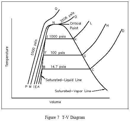
Consider the plot on the temperature-volume diagram of Figure 7, viewing the constant-pressure line that represents the states through which the water of the previous discussion passes as it is heated from the initial state of 14.7 psia and 60°F. Let state A represent the initial state and state B represent the start of the saturated liquid line (212°F). Therefore, line AB represents the process in which the liquid is heated from the initial temperature to the saturation temperature.
Point C is the saturated vapor state, and line BC is the constant-temperature process in which the change of phase from liquid to vapor occurs. Line CD represents the process in which the steam is super-heated at constant pressure. Temperature and volume both increase during the process.
Now let the process take place at a constant pressure of 100 psia, beginning from an initial temperature of 60°F. Point E represents the initial state, the specific volume being slightly less than 14.7 psia and 60°F. Vaporization now begins at point F, where the temperature is 327.8°F. Point G is the saturated-vapor state, and line GH is the constant-pressure process in which the steam is superheated.
In a similar manner, a constant pressure of 1000 psia is represented by line IJKL, the saturation temperature being 544.6°F.
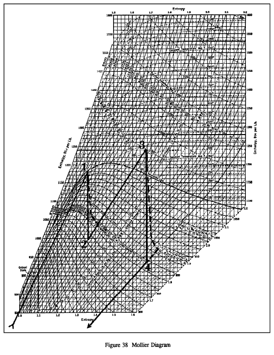
It is sometimes useful to plot on the Mollier diagram the processes that occur during the cycle. This is done on Figure 38. The numbered points on Figure 38 correspond to the numbered points on Figures 35 and 36. Because the Mollier diagram is a plot of the conditions existing for water in vapor form, the portions of the plot which fall into the region of liquid water do not show up on the Mollier diagram. The following conditions were used in plotting the curves on Figure 38.
Point 1: Saturated steam at 540oF
Point 2: 82.5% quality at exit of HP turbine
Point 3: Temperature of superheated steam is 440oF
Point 4: Condenser vacuum is 1 psia
The solid lines on Figure 38 represent the conditions for a cycle which uses ideal turbines as verified by the fact that no entropy change is shown across the turbines. The dotted lines on Figure 38 represent the path taken if real turbines were considered, in which case an increase in entropy is evident.
THERMODYNAMIC PROPERTIES
Mass and Weight
Specific Volume
Density
Specific Gravity
Humidity
Intensive and Extensive Properties
Summary
TEMPERATURE AND PRESSURE MEASUREMENTS
Temperature
Temperature Scales
Pressure
Pressure Scales
Summary
ENERGY, WORK, AND HEAT
Energy
Potential Energy
Kinetic Energy
Specific Internal Energy
Specific P-V Energy
Specific Enthalpy
Work
Heat
Entropy
Energy and Power Equivalences
Summary
THERMODYNAMIC SYSTEMS AND PROCESSES
Thermodynamic Systems and Surroundings
Types of Thermodynamic Systems
Thermodynamic Equilibrium
Control Volume
Steady State
Thermodynamic Process
Cyclic Process
Reversible Process
Irreversible Process
Adiabatic Process
Isentropic Process
Polytropic Process
Throttling Process
Summary
CHANGE OF PHASE
Classification of Properties
Saturation
Saturated and Subcooled Liquids
Quality
Moisture Content
Saturated and Superheated Vapors
Constant Pressure Heat Addition
Critical Point
Fusion
Sublimation
Triple Point
Condensation
Summary
PROPERTY DIAGRAMS AND STEAM TABLES
Property Diagrams
Pressure-Temperature (P-T) Diagram
Pressure-Specific Volume (P-v) Diagram
Pressure-Enthalpy (P-h) Diagram
Enthalpy-Temperature (h-T) Diagram
Temperature-Entropy (T-s) Diagram
Temperature-Entropy (T-s) Diagram
Steam Tables
Summary
FIRST LAW OF THERMODYNAMICS
First Law of Thermodynamics
Summary
SECOND LAW OF THERMODYNAMICS
Second Law of Thermodynamics
Entropy
Carnot’s Principle
Carnot Cycle
Diagrams of Ideal and Real Processes
Power Plant Components
Heat Rejection
Typical Steam Cycle
Causes of Inefficiency
Summary
COMPRESSION PROCESSES
Boyle’s and Charles’ Law
Ideal Gas Law
Fluid
Compressibility of Fluids
Constant Pressure Process
Constant Volume Process
Effects of Pressure Changes on Fluid Properties
Effects of Temperature Changes on Fluid Properties
Summary
APPENDIX A Thermodynamics
Volume 2 of 3
Module 2 - Heat Transfer
-Explanation- This module describes conduction, convection, and radiation heat transfer. The module also explains how specific parameters can affect the rate of heat transfer.
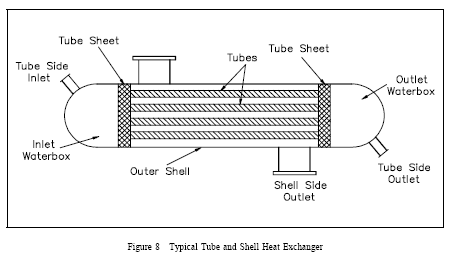
Single-phase heat exchangers are usually of the tube-and-shell type; that is, the exchanger consists of a set of tubes in a container called a shell (Figure 8). At the ends of the heat exchanger, the tube-side fluid is separated from the shell-side fluid by a tube sheet. The design of two-phase exchangers is essentially the same as that of single-phase exchangers.
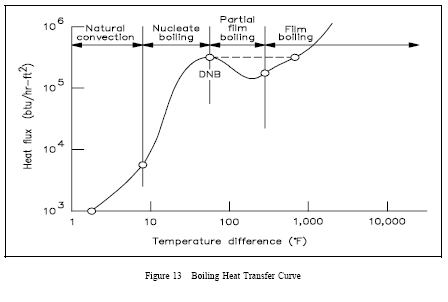
Four regions are represented in Figure 13. The first and second regions show that as heat flux increases, the temperature difference (surface to fluid) does not change very much. Better heat transfer occurs during nucleate boiling than during natural convection. As the heat flux increases, the bubbles become numerous enough that partial film boiling (part of the surface being blanketed with bubbles) occurs. This region is characterized by an increase in temperature difference and a decrease in heat flux. The increase in temperature difference thus causes total film boiling, in which steam completely blankets the heat transfer surface.
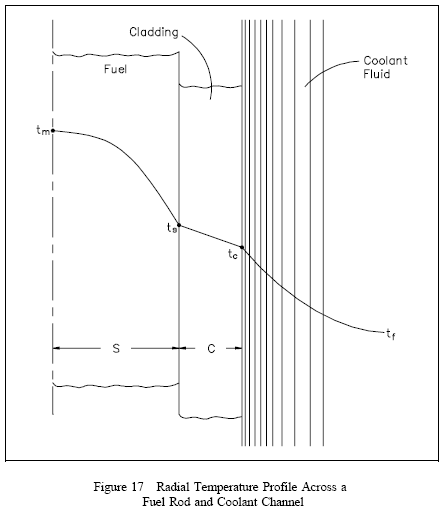
A radial temperature profile across a reactor core (assuming all channel coolant flows are equal) will basically follow the radial power distribution. The areas with the highest heat generation rate (power) will produce the most heat and have the highest temperatures. A radial temperature profile for an individual fuel rod and coolant channel is shown in Figure 17. The basic shape of the profile will be dependent upon the heat transfer coefficient of the various materials involved. The temperature differential across each material will have to be sufficient to transfer the heat produced. Therefore, if we know the heat transfer coefficient for each material and the heat flux, we can calculate peak fuel temperatures for a given coolant temperature.
HEAT TRANSFER TERMINOLOGY
Heat and Temperature
Heat and Work
Modes of Transferring Heat
Heat Flux
Thermal Conductivity
Log Mean Temperature Difference
Convective Heat Transfer Coefficient
Overall Heat Transfer Coefficient
Bulk Temperature
Summary
CONDUCTION HEAT TRANSFER
Conduction
Conduction-Rectangular Coordinates
Equivalent Resistance Method
Electrical Analogy
Conduction-Cylindrical Coordinates
Summary
CONVECTION HEAT TRANSFER
Convection
Overall Heat Transfer Coefficient
Convection Heat Transfer
Summary
RADIANT HEAT TRANSFER
Thermal Radiation
Black Body Radiation
Emissivity
Radiation Configuration Factor
Summary
HEAT EXCHANGERS
Heat Exchangers
Parallel and Counter-Flow Designs
Non-Regenerative Heat Exchanger
Regenerative Heat Exchanger
Cooling Towers
Log Mean Temperature Difference Application to Heat Exchangers
Overall Heat Transfer Coefficient
Summary
BOILING HEAT TRANSFER
Boiling
Nucleate Boiling
Bulk Boiling
Film Boiling
Departure from Nucleate Boiling and Critical Heat Flux
Summary
HEAT GENERATION
Heat Generation
Flux Profiles
Thermal Limits
Average Linear Power Density
Maximum Local Linear Power Density
Temperature Profiles
Volumetric Thermal Source Strength
Fuel Changes During Reactor Operation
Summary
DECAY HEAT
Reactor Decay Heat Production
Calculation of Decay heat
Decay Heat Limits
Decay Heat Removal
Summary
Volume 3 of 3
Module 3 - Fluid Flow
-Explanation- This module describes the relationship between the different types of energy in a fluid stream through the use of Bernoulli's equation. The module also discusses the causes of head loss in fluid systems and what factors affect head loss.
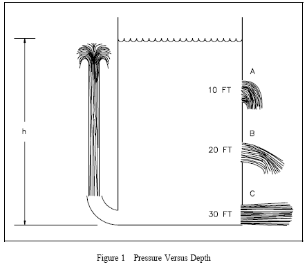
As shown in Figure 1 the pressure at different levels in the tank varies and this causes the fluid to leave the tank at varying velocities. Pressure was defined to be force per unit area. In the case of this tank, the force is due to the weight of the water above the point where the pressure is being determined.
Flow Velocity Profiles
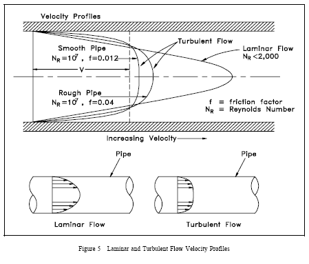
Not all fluid particles travel at the same velocity within a pipe. The shape of the velocity curve (the velocity profile across any given section of the pipe) depends upon whether the flow is laminar or turbulent. If the flow in a pipe is laminar, the velocity distribution at a cross section will be parabolic in shape with the maximum velocity at the center being about twice the average velocity in the pipe. In turbulent flow, a fairly flat velocity distribution exists across the section of pipe, with the result that the entire fluid flows at a given single value. Figure 5 helps illustrate the above ideas. The velocity of the fluid in contact with the pipe wall is essentially zero and increases the further away from the wall.
Note from Figure 5 that the velocity profile depends upon the surface condition of the pipe wall. A smoother wall results in a more uniform velocity profile than a rough pipe wall.
CONTINUITY EQUATION
Introduction
Properties of Fluids
Buoyancy
Compressibility
Relationship Between Depth and Pressure
Pascal’s Law
Control Volume
Volumetric Flow Rate
Mass Flow Rate
Conservation of Mass
Steady-State Flow
Continuity Equation
Summary
LAMINAR AND TURBULENT FLOW
Flow Regimes
Laminar Flow
Turbulent Flow
Flow Velocity Profiles
Average (Bulk) Velocity
Viscosity
Ideal Fluid
Reynolds Number
Summary
BERNOULLI’S EQUATION
General Energy Equation
Simplified Bernoulli Equation
Head
Energy Conversions in Fluid Systems
Restrictions on the Simplified Bernoulli Equation
Extended Bernoulli
Application of Bernoulli’s Equation to a Venturi
Summary
HEAD LOSS
Head Loss
Friction Factor
Darcy’s Equation
Minor Losses
Equivalent Piping Length
Summary
NATURAL CIRCULATION
Forced and Natural Circulation
Thermal Driving Head
Conditions Required for Natural Circulation
Example of Natural Circulation Cooling
Flow Rate and Temperature Difference
Summary
TWO-PHASE FLUID FLOW
Two-Phase Fluid Flow
Flow Instability
Pipe Whip
Water Hammer
Pressure spike
Steam Hammer
Operational Considerations
Summary
CENTRIFUGAL PUMPS
Energy Conversion in a Centrifugal Pump
Operating Characteristics of a Centrifugal Pump
Cavitation
Net Positive Suction Head
Pump Laws
System Characteristic Curve
System Operating Point
System Use of Multiple Centrifugal Pumps
Centrifugal Pumps in Parallel
Centrifugal Pumps in Series
Summary
APPENDIX B Fluid Flow
DOE Fundamentals Handbook - Thermodynamics, Heat Transfer, and Fluid Flow $13.95
The Thermodynamics, Heat Transfer, and Fluid Flowhandbook explains all you need to know about Thermodynamics and the three modes of heat transfer: conduction, convection and radiation. If you plan to do any solar heating experiments, or just want to understand and improve your home’s heating systems, this book will prove INVALUABLE. The handbook also describes the properties of fluids, the relationship between the different types of energy in a fluid stream through the use of Bernoulli's equation and discusses the causes of head loss in fluid systems and the factors that affect head loss. This book will provide you with the basic understanding of Thermodynamics, Heat Transfer and Fluid Flow needed to be part of the hydrogen revolution.


