Science / Chemistry / Mathematics Texts

DOE Fundamentals Handbook - Mechanical Science $13.95
The DOE Fundamentals Handbook - Mechanical Science consists of five modules that are contained in two volumes. The Mechanical Science handbook includes detailed explanations of Operational Terminology, as well as, information on diesel engines, heat exchangers, pumps and valves. This Book will provide YOU with a technical foundation essential for understanding the construction and operation of mechanical components such as Flywheels, Camshafts and Fuel Systems. The Mechanical Science handbook contains the information that YOU need about basic systems and equipment operations which are associated with various Hydrogen Science applications and experiments.
DOE FUNDAMENTALS HANDBOOK MECHANICAL SCIENCE
VOLUMES 1-2
The Department of Energy (DOE) Fundamentals Handbooks consist of ten academic subjects, which include Mathematics; Classical Physics; Thermodynamics, Heat Transfer, and Fluid Flow; Instrumentation and Control; Electrical Science; Material Science; Mechanical Science; Chemistry; Engineering Symbology, Prints, and Drawings; and Nuclear Physics and Reactor Theory. The handbooks were first published as Reactor Operator Fundamentals Manuals in 1985 for use by DOE category A reactors. The subject areas, subject matter content, and level of detail of the Reactor Operator Fundamentals Manuals were determined from several sources and prepared by the DOE Training Coordination Program. Each handbook contains an abstract, a foreword, an overview, learning objectives, and text material, and is divided into modules.
The Mechanical Science Handbook was originally developed to assist nuclear facility operating contractors in providing operators, maintenance personnel, and the technical staff with the necessary fundamentals training to ensure a basic understanding of mechanical components and mechanical science. The handbook includes information on diesel engines, heat exchangers, pumps, valves, and miscellaneous mechanical components. This information will provide individuals with a foundation for understanding the construction and operation of mechanical components that are associated with various DOE nuclear facility operations and maintenance. The Mechanical Science handbook presents enough information to provide the reader with the fundamental knowledge necessary to understand the advanced theoretical concepts presented in other subject areas, and to
understand basic system and equipment operation.
The Mechanical Science handbook consists of five modules that are contained in two volumes. The following is a brief description of the information presented in each module of the handbook.
Volume 1 of 2
Module 1 - Diesel Engine Fundamentals
-Explanation- Provides information covering the basic operating principles of 2-cycle and 4-cycle diesel engines. Includes operation of engine governors, fuel ejectors, and typical engine protective features.
Major Components of a Diesel Engine
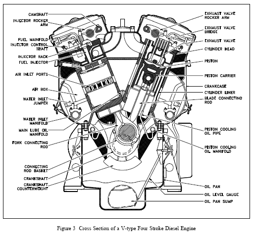
To understand how a diesel engine operates, an understanding of the major components and how they work together is necessary. Figure 2 is an example of a medium-sized, four-stroke, supercharged, diesel engine with inlet ports and exhaust valves. Figure 3 provides a cross section of a similarly sized V-type diesel engine.
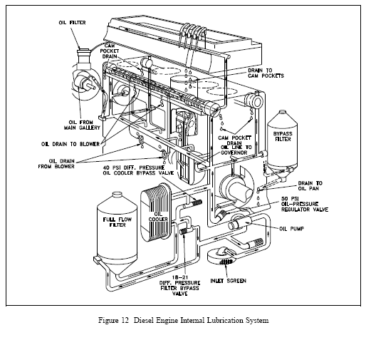
Oil is accumulated and stored in the engine's oil pan where one or more oil pumps take a suction and pump the oil through one or more oil filters as shown in Figure 12. The filters clean the oil and remove any metal that the oil has picked up due to wear. The cleaned oil then flows up into the engine's oil galleries. A pressure relief valve(s) maintains oil pressure in the galleries and returns oil to the oil pan upon high pressure. The oil galleries distribute the oil to all the bearing surfaces in the engine.
DIESEL ENGINES
Introduction
History
Diesel Engines
Major Components of a Diesel Engine
Diesel Engine Support Systems
Exhaust System
Operational Terminology
Summary
FUNDAMENTALS OF THE DIESEL CYCLE
The Basic Diesel Cycles
The Four-Stoke Cycle
The Two-Stroke Cycle
Summary
DIESEL ENGINE SPEED, FUEL CONTROLS, AND PROTECTION
Engine Control
Fuel Injectors
Governor
Operation of a Governor
Starting Circuits
Engine Protection
Summary
Module 2 - Heat Exchangers
-Explanation- Describes the construction of plate heat exchangers and tube and shell heat exchangers. Describes the flow patterns and temperature profiles in parallel flow, counter flow, and cross flow heat exchangers.
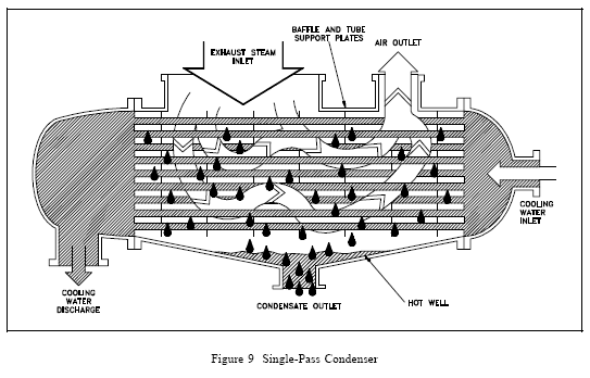
There are different condenser designs, but the most common, at least in the large power generation facilities, is the straight-through, single-pass condenser illustrated Figure 9. This condenser design provides cooling water flow through straight tubes from the inlet water box on one end, to the outlet water box on the other end. The cooling water flows once through the condenser and is termed a single pass. The separation between the water box areas and the steam condensing area is accomplished by a tube sheet to which the cooling water tubes are attached. The cooling water tubes are supported within the condenser by the tube support sheets. Condensers normally have a series of baffles that redirect the steam to minimize direct impingement on the cooling water tubes. The bottom area of the condenser is the hotwell, as shown in Figure 9. This is where the condensate collects and the condensate pump takes its suction. If noncondensable gasses are allowed to build up in the condenser, vacuum will decrease and the saturation temperature at which the steam will condense increases.
TYPES OF HEAT EXCHANGERS
Introduction
Types of Heat Exchanger Construction
Types of Heat Exchangers
Comparison of the Types of Heat Exchangers
Summary
HEAT EXCHANGER APPLICATIONS
Introduction
Preheater
Radiator
Air Conditioner Evaporator and Condenser
Large Steam System Condensers
Summary
Module 3 - Pumps
-Explanation- Explains the operation of centrifugal and positive displacement pumps. Topics include net positive suction head, cavitation, gas binding, and pump characteristic curves.
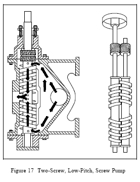
The complete assembly and the usual flow path are shown in Figure 17. Liquid is trapped at the outer end of each pair of screws. As the first space between the screw threads rotates away from the opposite screw, a one-turn, spiral-shaped quantity of liquid is enclosed when the end of the screw again meshes with the opposite screw. As the screw continues to rotate, the entrapped spiral turns of liquid slide along the cylinder toward the center discharge space while the next slug is being entrapped. Each screw functions similarly, and each pair of screws discharges an equal quantity of liquid in opposed streams toward the center, thus eliminating hydraulic thrust. The removal of liquid from the suction end by the screws produces a reduction in pressure, which draws liquid through the suction line.
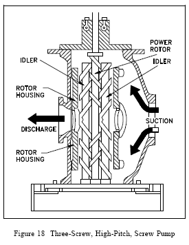
The three-screw, high-pitch, screw pump, shown in Figure 18, has many of the same elements as the two-screw, low-pitch, screw pump, and their operations are similar. Three screws, oppositely threaded on each end, are employed. They rotate in a triple cylinder, the two outer bores of which overlap the center bore. The pitch of the screws is much higher than in the low pitch screw pump; therefore, the center screw, or power rotor, is used to drive the two outer idler rotors directly without external timing gears. Pedestal bearings at the base support the weight of the rotors and maintain their axial position. The liquid being pumped enters the suction opening, flows through passages around the rotor housing, and through the screws from each end, in opposed streams, toward the center discharge. This eliminates unbalanced hydraulic thrust. The screw pump is used for pumping viscous fluids, usually lubricating, hydraulic, or fuel oil.
CENTRIFUGAL PUMPS
Introduction
Diffuser
Impeller Classification
Centrifugal Pump Classification by Flow
Multi-Stage Centrifugal Pumps
Centrifugal Pump Components
Summary
CENTRIFUGAL PUMP OPERATION
Introduction
Cavitation
Net Positive Suction Head
Preventing Cavitation
Centrifugal Pump Characteristic Curves
Centrifugal Pump Protection
Gas Binding
Priming Centrifugal Pumps
Summary
POSITIVE DISPLACEMENT PUMPS
Introduction
Principle of Operation
Reciprocating Pumps
Rotary Pumps
Diaphragm Pumps
Positive Displacement Pump Characteristic Curves
Positive Displacement Pump Protection
Summary
Volume 2 of 2
Module 4 - Valves
-Explanation- Introduces the functions of the basic parts common to most types of valves. Provides information on applications of many types of valves. Types of valves covered include gate valves, globe valves, ball valves, plug valves, diaphragm valves, reducing valves, pinch valves, butterfly valves, needle valves, check valves, and safety/relief valves.
Gate Valves
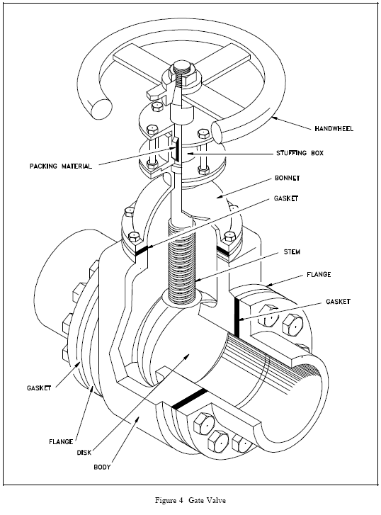
A gate valve is a linear motion valve used to start or stop fluid flow; however, it does not regulate or throttle flow. The name gate is derived from the appearance of the disk in the flow stream. Figure 4 illustrates a gate valve.
The disk of a gate valve is completely removed from the flow stream when the valve is fully open. This characteristic offers virtually no resistance to flow when the valve is open. Hence, there is little pressure drop across an open gate valve.
When the valve is fully closed, a disk-to-seal ring contact surface exists for 360°, and good sealing is provided. With the proper mating of a disk to the seal ring, very little or no leakage occurs across the disk when the gate valve is closed.
Reducing Valves
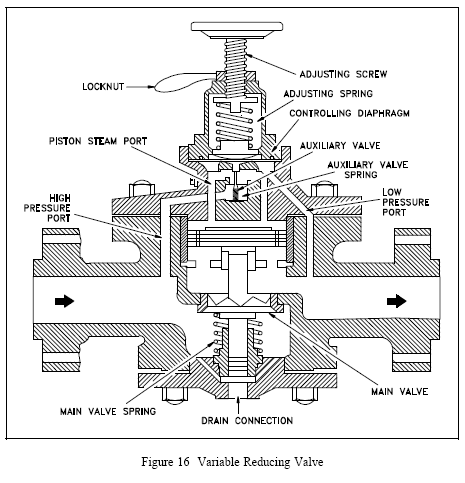
Reducing valves automatically reduce supply pressure to a preselected pressure as long as the supply pressure is at least as high as the selected pressure. As illustrated in Figure 16, the principal parts of the reducing valve are the main valve; an upward-seating valve that has a piston on top of its valve stem, an upward-seating auxiliary (or controlling) valve, a controlling diaphragm, and an adjusting spring and screw.
The controlling diaphragm transmits a downward force that tends to open the auxiliary valve. The downward force is exerted by the adjusting spring, which is controlled by the adjusting screw. Reduced pressure from the main valve outlet is bled back to a chamber beneath the diaphragm to counteract the downward force of the adjusting spring. The position of the auxiliary valve, and ultimately the position of the main valve, is determined by the position of the diaphragm. The position of the diaphragm is determined by the strength of the opposing forces of the downward force of the adjusting spring versus the upward force of the outlet reduced pressure. Other reducing valves work on the same basic principle, but may use gas, pneumatic, or hydraulic controls in place of the adjusting spring and screw.
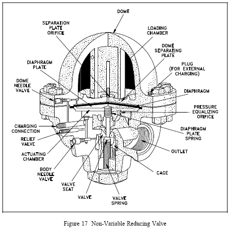
Non-variable reducing valves, illustrated in Figure 17, replace the adjusting spring and screw with a pre-pressurized dome over the diaphragm. The valve stem is connected either directly or indirectly to the diaphragm. The valve spring below the diaphragm keeps the valve closed. As in the variable valve, reduced pressure is bled through an orifice to beneath the diaphragm to open the valve. Valve position is determined by the strength of the opposing forces of the downward force of the pre-pressurized dome versus the upward force of the outlet-reduced pressure.
VALVE FUNCTIONS AND BASIC PARTS
Introduction
Valve Body
Valve Bonnet
Valve Trim
Valve Actuator
Valve Packing
Introduction to the Types of Valves
Summary
TYPES OF VALVES
Gate Valves
Gate Valve Disk Design
Gate Valve Stem Design
Gate Valve Seat Design
Globe Valves
Globe Valve Body Designs
Globe Valve Disks
Globe Valve Disk and Stem Connections
Globe Valve Seats
Globe Valve Direction of Flow
Ball Valves
Ball Valve Stem Design
Ball Valve Bonnet Design
Ball Valve Position
Plug Valves
Plug Ports
Multiport Plug Valves
Plug Valve Disks
Lubricated Plug Valve Design
Nonlubricated Plugs .. 23
Manually Operated Plug Valve Installation
Plug Valve Glands
Diaphragm Valves
Diaphragm Construction
Diaphragm Valve Stem Assemblies
Diaphragm Valve Bonnet Assemblies
Reducing Valves
Pinch Valves
Pinch Valve Bodies
Butterfly Valves
Butterfly Valve Seat Construction
Butterfly Valve Body Construction
Butterfly Valve Disk and Stem Assemblies
Needle Valves
Needle Valve Applications
Needle Valve Body Designs
Check Valves
Swing Check Valves
Tilting Disk Check Valves
Lift Check Valves
Piston Check Valves
Butterfly Check Valves
Stop Check Valves
Relief And Safety Valves
Pilot-Operated Relief Valves
Summary
VALVE ACTUATORS
Introduction
Manual, Fixed, and Hammer Actuators
Electric Motor Actuators
Pneumatic Actuators
Hydraulic Actuators
Self-Actuated Valves
Solenoid Actuated Valves
Speed of Power Actuators
Valve Position Indication
Summary
Module 5 - Miscellaneous Mechanical Components
-Explanation- Provides information on significant mechanical devices that have widespread application in nuclear facilities but do not fit into the categories of components covered by the other modules. These include cooling towers, air compressors, demineralizers, filters, strainers, etc.
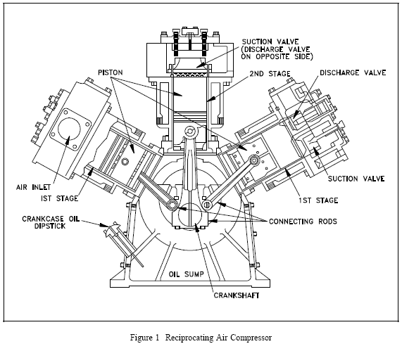 |
Reciprocating Compressors The reciprocating air compressor, illustrated in Figure 1, is the most common design employed today. The reciprocating compressor normally consists of the following elements. a. The compressing element, consisting of air cylinders, heads and pistons, and air inlet and discharge valves. b. A system of connecting rods, piston rods, crossheads, and a crankshaft and flywheel for transmitting the power developed by the driving unit to the air cylinder piston. c. A self-contained lubricating system for bearings, gears, and cylinder walls, including a reservoir or sump for the lubricating oil, and a pump, or other means of delivering oil to the various parts. On some compressors a separate force-fed lubricator is installed to supply oil to the compressor cylinders. d. A regulation or control system designed to maintain the pressure in the discharge line and air receiver (storage tank) within a predetermined range of pressure. e. An unloading system, which operates in conjunction with the regulator, to reduce or eliminate the load put on the prime mover when starting the unit. |
Boilers
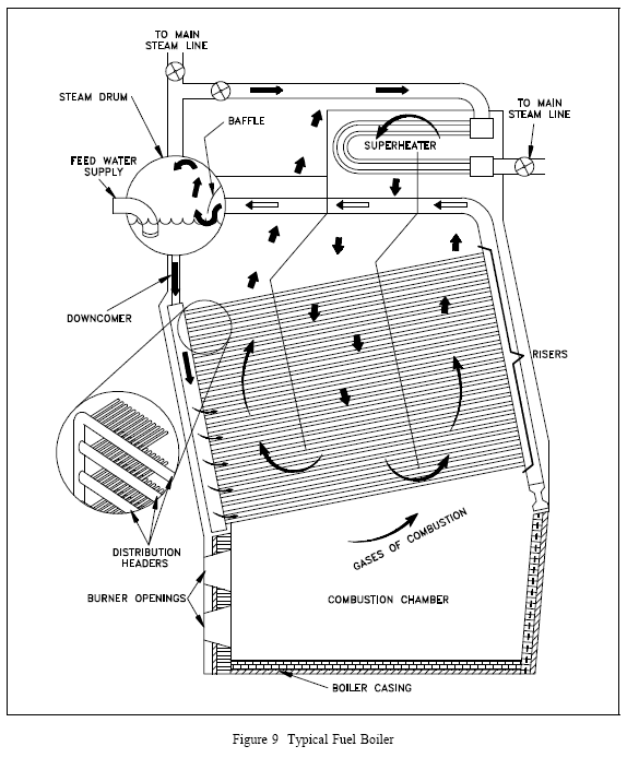
Two distinct heat sources used for boilers are electric probes and burned fuel (oil, coal, etc.) This chapter will use fuel boilers to illustrate the typical design of boilers. Refer to Figure 9 during the following discussion.
The boiler has an enclosed space where the fuel combustion takes place, usually referred to as the furnace or combustion chamber. Air is supplied to combine with the fuel, resulting in combustion. The heat of combustion is absorbed by the water in the risers or circulating tubes. The density difference between hot and cold water is the driving force to circulate the water back to the steam drum. Eventually the water will absorb sufficient heat to produce steam.
Steam leaves the steam drum via a baffle, which causes any water droplets being carried by the steam to drop out and drain back to the steam drum. If superheated steam is required, the steam may then travel through a superheater. The hot combustion gasses from the furnace will heat the steam through the superheater's thin tube walls. The steam then goes to the steam supply system and the various steam loads.
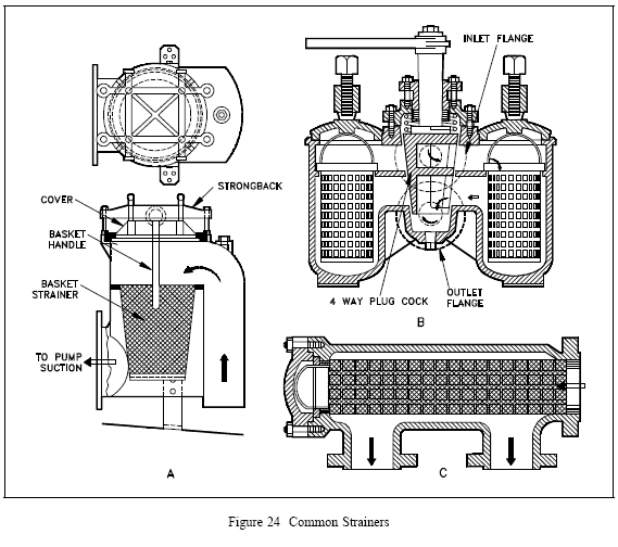
Figure 24 illustrates three additional common types of strainers. Part A shows a typical sump pump suction bucket strainer located in the sump pump suction line between the suction manifold and the pump. Any debris that enters the piping is collected in the strainer basket. The basket can be removed for cleaning by loosening the strongback screws, removing the cover, and lifting the basket out by its handle.
Part B of Figure 24 shows a duplex oil strainer commonly used in fuel oil and lubricating oil lines, where it is essential to maintain an uninterrupted flow of oil. The flow may be diverted from one basket to the other, while one is being cleaned.
Part C of Figure 24 shows a manifold steam strainer. This type of strainer is desirable where space is limited, because it eliminates the use of separate strainers and their fittings. The cover is located so that the strainer basket can be removed for cleaning.
AIR COMPRESSORS
Introduction
Reciprocating Compressors
Rotary Compressors
Centrifugal Compressors
Compressor Coolers
Hazards of Compressed Air
Summary
HYDRAULICS
Introduction
Pressure and Force
Hydraulic Operation
Hazards
Summary
BOILERS
Introduction
Boilers
Fuel Boiler Components
Summary
COOLING TOWERS
Purpose
Induced Draft Cooling Towers
Forced Draft Cooling Towers
Natural Convection Cooling Towers
Summary
DEMINERALIZERS
Purpose of Demineralizers
Demineralizers
Single-Bed Demineralizers
Single-Bed Regeneration
Mixed-Bed Demineralizer
Mixed-Bed Regeneration
External Regeneration
Summary
PRESSURIZERS
Introduction
General Description
Dynamic Pressurizers
Construction
Operation
Summary
STEAM TRAPS
General Operation
Ball Float Steam Trap
Bucket Steam Trap
Thermostatic Steam Traps
Bellows-Type Steam Trap
Impulse Steam Trap
Orifice-Type Steam Trap
Summary
FILTERS AND STRAINERS
Introduction
Cartridge Filters
Precoat Filters
Backwashing Precoat Filters
Deep-Bed Filters
Metal-Edge Filters
Strainers
Backwashing
Summary

DOE Fundamentals Handbook - Mechanical Science $13.95
The DOE Fundamentals Handbook - Mechanical Science consists of five modules that are contained in two volumes. The Mechanical Science handbook includes detailed explanations of Operational Terminology, as well as, information on diesel engines, heat exchangers, pumps and valves. This Book will provide YOU with a technical foundation essential for understanding the construction and operation of mechanical components such as Flywheels, Camshafts and Fuel Systems. The Mechanical Science handbook contains the information that YOU need about basic systems and equipment operations which are associated with various Hydrogen Science applications and experiments.


