Science / Chemistry / Mathematics Texts
DOE Fundamentals Handbook - Electrical Science $17.95
The Electrical Science Handbook begins with a clear, concise introduction to important terminology and basic electrical concepts including Direct Current (DC) electrical circuits and more. Subsequent sections go on to introduce rules associated with the reactive components of inductance and capacitance, batteries, circuit arrangements, voltage production of various generators, voltage regulators electrical motor characteristics, transformer theory and electrical distribution systems. The information in the handbook is presented to provide a foundation for applying engineering concepts. At 450 pages, this handbook is of one of the finest books on electricity and electrical science that you’ll find. There is NO better book out there anywhere to keep on-hand as your personal reference book for detailed explanations of A/C-D/C, ohm, volts, ampere, power, watts, wire, math and just about anything else you might need to know about the electrical field. Understand Electricity!!! The Electrical Science handbook presents more than enough information to provide YOU with the fundamental knowledge needed to understand the advanced theoretical concepts that drive forward frontiers of energy sciences.


DOE FUNDAMENTALS HANDBOOK ELECTRICAL SCIENCE
VOLUMES 1-4
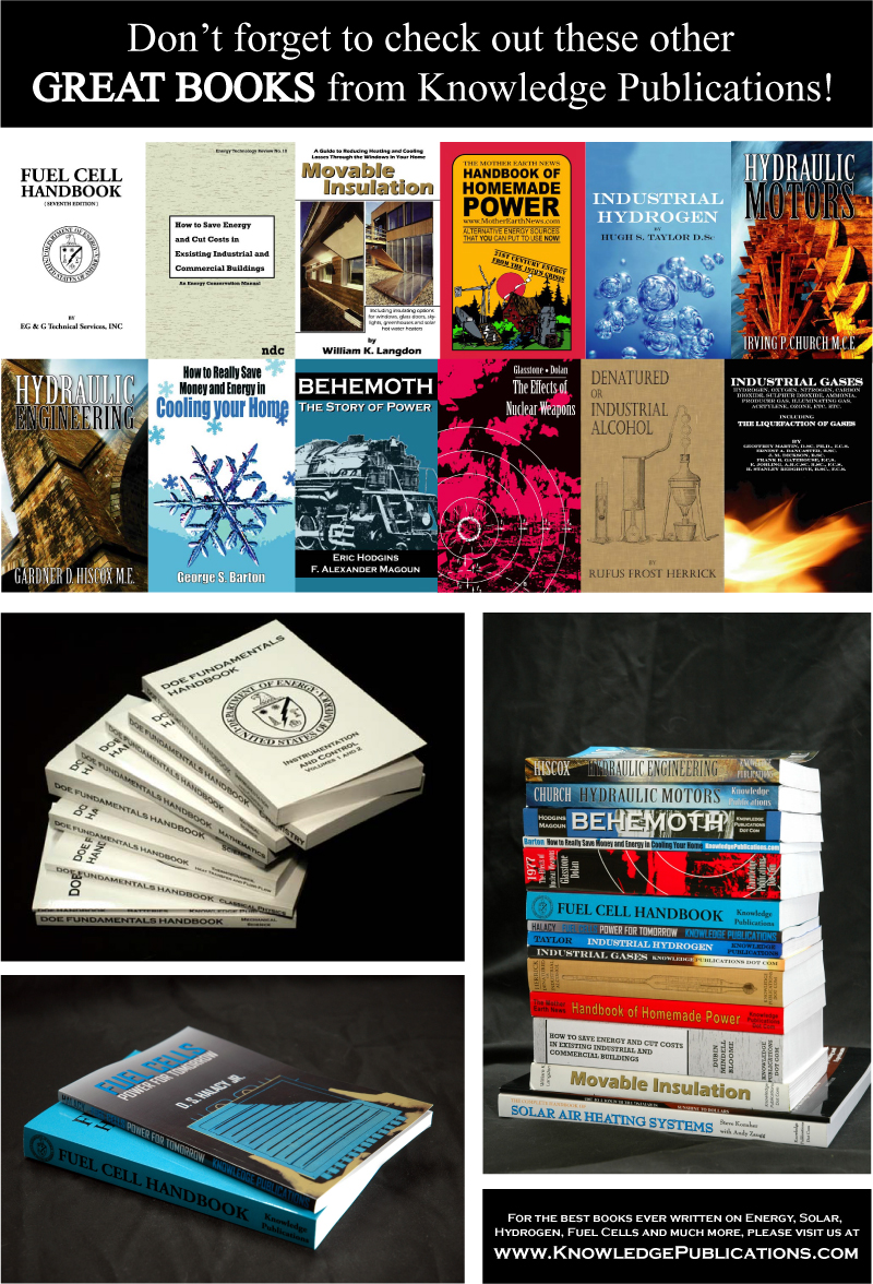
The Department of Energy (DOE) Fundamentals Handbooks consist of ten academic subjects, which include Mathematics; Classical Physics; Thermodynamics, Heat Transfer, and Fluid Flow; Instrumentation and Control; Electrical Science; Material Science; Mechanical Science; Chemistry; Engineering Symbology, Prints, and Drawings; and Nuclear Physics and Reactor Theory. The handbooks were first published as Reactor Operator Fundamentals Manuals in 1985 for use by DOE category A reactors. The subject areas, subject matter content, and level of detail of the Reactor Operator Fundamentals Manuals were determined from several sources and prepared by the DOE Training Coordination Program. Each handbook contains an abstract, a foreword, an overview, learning objectives, and text material, and is divided into modules.
The Department of Energy Fundamentals Handbook entitled Electrical Science was prepared as an information resource for personnel who are responsible for the operation of the Department's nuclear facilities. The information in the handbook is presented to provide a foundation for applying engineering concepts. The Electrical Science handbook presents more than enough information to provide the reader with a fundamental knowledge level sufficient to understand the advanced theoretical concepts presented in other subject areas, and to better understand basic system and equipment operations.
The Electrical Science handbook consists of fifteen modules that are contained in four volumes. The following is a brief description of the information presented in each module of the handbook along with some selected figures included in the handbook.
Volume 1 of 4
Module 1 - Basic Electrical Theory
- Explanation- This module describes basic electrical concepts and introduces electrical terminology.
ATOM AND ITS FORCES
The Atom
Electrostatic Force
The First Law of Electrostatics
Electrostatic Field
Potential Difference
Free Electrons
Summary
ELECTRICAL TERMINOLOGY
Conductors
Insulators
Resistors
Voltage
Current
Real and Ideal Sources
Summary
UNITS OF ELECTRICAL MEASUREMENT
System Internationale (SI) Metric System
Voltage
Current
Resistance
Ohm’s Law
Conductance
Inductance
Capacitance
Summary
METHODS OF PRODUCING VOLTAGE (ELECTRICITY)
Electrochemistry
Static Electricity
Magnetic Induction
Piezoelectric Effect
Thermoelectricity
Photoelectric Effect
Thermionic Emission
Summary
MAGNETISM
Magnetism
Magnetic Flux
Magnetic Flux Density
Magnetic Materials
Electromagnetism
Polarity of a Single Conductor
Magnetic Field and Polarity of a Coil
Magnetomotive Force
Field Intensity
Reluctance
Summary
MAGNETIC CIRCUITS
Magnetic Circuits
BH Magnetization Curve
Hysteresis
Magnetic Induction
Faraday’s Law of Induced Voltage
Lenz’s Law
Summary
Module 2 - Basic DC Theory
-Explanation- This module describes the basic concepts of direct current (DC) electrical circuits and discusses the associated terminology.
Parallel circuits are those circuits which have two or more components connected across the same voltage source (Figure 17). Resistors R1, R2, and R3 are in parallel with each other and the source. Each parallel path is a branch with its own individual current. When the current leaves the source V, part I1 of IT will flow through R1; part I2 will flow through R2; and part I3 will flow through R3. Current through each branch can be different; however, voltage throughout the circuit will be equal.
V=V1=V2=V3.
DC SOURCES
Batteries
DC Generator
Thermocouples
Rectifiers
Forward Bias
Reverse Bias
Half-Wave Rectifier Circuit
Full-Wave Rectifier Circuit
Summary
DC CIRCUIT TERMINOLOGY
Schematic Diagram
One-Line Diagram
Block Diagram
Wiring Diagram
Resistivity
Temperature Coefficient of Resistance
Electric Circuit
Series Circuit
Parallel Circuit
Equivalent Resistance
Summary
BASIC DC CIRCUIT CALCULATIONS
Series Resistance
Parallel Currents
Resistance in Parallel
Simplified Formulas
Voltage Divider
Current Division
Summary
VOLTAGE POLARITY AND CURRENT DIRECTION
Conventional and Electron Flow
Polarities
Summary
KIRCHHOFF’S LAWS
Kirchhoff’s Laws
Kirchhoff’s Voltage Law
Applying Kirchhoff’s Voltage Law
Kirchhoff’s Current Law
Summary
DC CIRCUIT ANALYSIS
Loop Equations
Node Equations
Series-Parallel Circuit Analysis
Y and Delta Network Calculation
Summary
DC CIRCUIT FAULTS
Open Circuit (Series)
Open Circuit (Parallel)
Short Circuit (Series)
Short Circuit (Parallel)
Summary
Volume 2 of 4
Module 3 - DC Circuits
-Explanation- This module introduces the rules associated with the reactive components of inductance and capacitance and how they affect DC circuits.
INDUCTANCE
Inductors
Summary
CAPACITANCE
Capacitor
Capacitance
Types of Capacitors
Capacitors in Series and Parallel
Capacitive Time Constant
Summary
Module 4 - Batteries
-Explanation- This module introduces batteries and describes the types of cells used, circuit arrangements, and associated hazards.
Specific gravity is measured with a hydrometer. A simple hydrometer consists of a glass float inside a glass tube, as shown in Figure 1. The hydrometer float is weighted at one end and sealed at both ends. A scale calibrated in specific gravity is positioned lengthwise along the body of the float. The float is placed inside the glass tube, and the fluid to be tested is drawn into the tube. As the fluid is drawn into the tube, the hydrometer float will sink to a certain level in the fluid. The extent to which the hydrometer float protrudes above the level of the fluid depends on the specific gravity of the fluid. The reading on the float scale at the surface of the fluid is the specific gravity of the fluid.

Series Cells
When several cells are connected in series (Figure 7), the total voltage output of the battery is equal to the sum of the individual cell voltages. In the example of the battery in Figure 7, the four 1.5V cells provide a total of 6 volts. When we connect cells in series, the positive terminal of one cell is connected to the negative terminal of the next cell. The current flow through a battery connected in series is the same as for one cell.
BATTERY TERMINOLOGY
Voltaic Cell
Battery
Electrode
Electrolyte
Specific Gravity
Ampere-Hour
Summary
BATTERY THEORY
Batteries
Discharge and Charging of Lead-Acid Battery
Summary
BATTERY OPERATIONS
Series Cells
Parallel Cells
Primary Cell
Secondary Cells
Capacity
Internal Resistance
Shelf Life
Charge and Discharge
Summary
TYPES OF BATTERIES
Wet and Dry Cells
Carbon-Zinc Cell
Alkaline Cell
Nickel-Cadmium Cell
Edison Cell
Mercury Cell
Summary
BATTERY HAZARDS
Shorted Cell
Gas Generation
Battery Temperature
Summary
Module 5 - DC Generators
-Explanation- This module describes the types of DC generators and their application in terms of voltage production and load characteristics.
DC EQUIPMENT TERMINOLOGY
Terminal Voltage
Counter-Electromotive Force
Applied Voltage
Commutation
Summary
DC EQUIPMENT CONSTRUCTION
Armature
Rotor
Stator
Field
Summary
DC GENERATOR THEORY
Voltage Production
Theory of Operation
Commutator Action
Field Excitation
Terminal Voltage
DC Generator Ratings
Internal Losses
Copper Losses
Eddy-Current Losses
Hysteresis Losses
Mechanical Losses
Summary
DC GENERATOR CONSTRUCTION
Shunt-Wound DC Generators
Series-Wound DC Generators
Compound Generators
Summary
Module 6 - DC Motors
-Explanation- This module describes the types of DC motors and includes discussions of speed control, applications, and load characteristics.
Above the conductor on the left, the field caused by the conductor is in the opposite direction of the main field, and therefore, opposes the main field. Below the conductor on the left, the field caused by the conductor is in the same direction as the main field, and therefore, aids the main field. The net result is that above the conductor the main field is weakened, or flux density is decreased; below the conductor the field is strengthened, or flux density is increased. A force is developed on the conductor that moves the conductor in the direction of the weakened field (upward).
DC MOTOR THEORY
Inducing a Force on a Conductor
Theory of Operation
Torque
Generator Action in a Motor
DC Motor Speed
Summary
TYPES OF DC MOTORS
DC Motor Connections
Shunt-Wound Motor Operation
Shunt-Wound Motor Applications
Series-Wound Motor
Series-Wound Motor Applications
Compounded Motor
Summary
DC MOTOR OPERATION
Starting of DC Motors
DC Motor Ratings
Summary
Volume 3 of 4
Module 7 - Basic AC Theory
-Explanation- This module describes the basic concepts of alternating current (AC) electrical circuits and discusses the associated terminology.
AC GENERATION
Development of a Sine-Wave Output
Summary
AC GENERATION ANALYSIS
Effective Values
Phase Angle
Voltage Calculations
Current Calculations
Frequency Calculations
Summary
Module 8 - AC Reactive Components
-Explanation- This module describes inductance and capacitance and their effects on AC circuits.
INDUCTANCE
Inductive Reactance
Voltage and Current Phase Relationships in an Inductive Circuit
CAPACITANCE
Capacitors
Capacitive Reactance
Summary
IMPEDANCE
Impedance
Impedance in R-L Circuits
Impedance in R-C Circuits
Impedance in R-C-L Circuits
Summary
RESONANCE
Resonant Frequency
Series Resonance
Parallel Resonance
Summary
Module 9 - AC Power
-Explanation- This module presents power calculations for single-phase and three-phase AC circuits and includes the power triangle concept.
Three-phase equipment (motors, transformers, etc.) weighs less than single-phase equipment of the same power rating. They have a wide range of voltages and can be used for single-phase loads. Three-phase equipment is smaller in size, weighs less, and is more efficient than single-phase equipment.
Three-phase systems can be connected in two different ways. If the three common ends of each phase are connected at a common point and the other three ends are connected to a 3ö line, it is called a wye, or Y-, connection (Figure 11). If the three phases are connected in series to form a closed loop, it is called a delta connection.
POWER TRIANGLE
Power Triangle
Apparent Power
True Power
Reactive Power
Total Power
Power Factor
Power in Series R-L Circuit
Power in Parallel R-L Circuit
Power in Series R-C Circuit
Power in Parallel R-C Circuit
Power in Series R-C-L Circuit in Parallel R-C-L Circuit
Summary
THREE-PHASE CIRCUITS
Three-Phase Systems
Power in Balanced 3ö Loads
Unbalanced 3ö Loads
Summary
Module 10 - AC Generators
-Explanation- This module describes the operating characteristics of AC generators and includes terminology, methods of voltage production, and methods of paralleling AC generation sources.
AC GENERATOR COMPONENTS
Field
Armature
Prime Mover
Rotor
Stator
Slip Rings
Summary
AC GENERATOR THEORY
Theory of Operation
Losses in an AC Generator
Hysteresis Losses
Mechanical Losses
fficiency
Summary
AC GENERATOR OPERATION
Ratings
Paralleling AC Generators
Types of AC Generators
Three-Phase AC Generators
AC Generator Connections
Summary
Module 11 - Voltage Regulators
-Explanation- This module describes the basic operation and application of voltage regulators.
VOLTAGE REGULATORS
Purpose
Block Diagram Description
Sensing Circuit
Reference Circuit
Comparison Circuit
Amplification Circuit
Signal Output Circuit
Feedback Circuit
Changing Output Voltage
Summary
Volume 4 of 4
Module 12 - AC Motors
-Explanation- This module explains the theory of operation of AC motors and discusses the various types of AC motors and their application.
The induction motor rotor is made of a laminated cylinder with slots in its surface. The windings in the slots are one of two types. The most commonly used is the "squirrel-cage" rotor. This rotor is made of heavy copper bars that are connected at each end by a metal ring made of copper or brass. No insulation is required between the core and the bars because of the low voltages induced into the rotor bars. The size of the air gap between the rotor bars and stator windings necessary to obtain the maximum field strength is
small.
AC MOTOR THEORY
Principles of Operation
Rotating Field
Torque Production
Slip
Torque
Summary
AC MOTOR TYPES
Induction Motor
Single-Phase AC Induction Motors
Synchronous Motors
Starting a Synchronous Motor
Field Excitation
Summary
Module 13 - Transformers
-Explanation- This module introduces transformer theory and includes the types of transformers, voltage/current relationships, and application.
TRANSFORMER THEORY
Mutual Induction
Turns Ratio
Impedance Ratio
Efficiency
Theory of Operation
Voltage Ratio
Current Ratio
Three-Phase Transformer Connections
Delta Connection
Wye Connection
Combinations of Delta and Wye Transformer Connections
Transformer Losses and Efficiency
Transformer Operation Under No-Load
Coil Polarity
Summary
TRANSFORMER TYPES
Types of Transformers
Distribution Transformer
Power Transformer
Control Transformer
Auto Transformer
Isolation Transformer
Instrument Potential Transformer
Instrument Current Transformer
Summary
Module 14 - Test Instruments and Measuring Devices
-Explanation- This module describes electrical measuring and test equipment and includes the parameters measured and the principles of operation of common instruments.
The most commonly used sensing mechanism used in DC ammeters, voltmeters, and ohm meters is a current-sensing device called a D’Arsonval meter movement (Figure 1). The D’Arsonval movement is a DC moving coil-type movement in which an electromagnetic core is suspended between the poles of a permanent magnet.
The current measured is directed through the coils of the electromagnet so that the magnetic field produced by the current opposes the field of the permanent magnet and causes rotation of the core. The core is restrained by springs so that the needle will deflect or move in proportion to the current intensity. The more current applied to the core, the stronger the opposing field, and the larger the deflection, up to the limit of the current capacity of the coil. When the current is interrupted, the opposing field collapses, and the needle is returned to zero by the restraining springs. The limit of the current that can be applied to this type movement is
usually less than one milliampre.
METER MOVEMENTS
D’Arsonval Movement
Electrodynamometer Movement
Moving Iron Vane Movement
Summary
VOLTMETERS
Voltmeters
Summary
AMMETERS
Ammeters
Summary
OHM METERS
Ohm Meters
Summary
WATTMETERS
Wattmeters
Three-Phase Wattmeter
Summary
OTHER ELECTRICAL MEASURING DEVICES
Ampere-Hour Meter
Power Factor Meter
Ground Detector
Synchroscope
TEST EQUIPMENT
Multimeter
Megger
Summary
Module 15 - Electrical Distribution Systems
-Explanation- This module describes basic electrical distribution systems and includes characteristics of system design to ensure personnel and equipment safety.
When the electrically-operated stored energy circuit breaker is tripped, the spring is recharged by the spring charging motor so that the breaker is ready for the next closing operation. The manually-operated circuit breaker closing springs are normally compressed by a hand crank just prior to operation of the breaker. Figure 6 shows a large air circuit breaker which is classified as a manually-operated stored energy circuit breaker. The closing springs are compressed by pulling downward on the large operating handle on the front of the breaker. Closing this circuit breaker is accomplished manually by depressing the small closing lever. Tripping this circuit breaker is done by means of the tripping lever, located at the bottom front of the breaker.
SYSTEM COMPONENTS AND PROTECTION DEVICES
Single (One-Line) Diagram
Commercial or Utility Power
Diesel Power
Failure-Free Power
Neutral Grounding
Voltage Class
Protective Relays
Overlapping Protective Zones
Fuses
Summary
CIRCUIT BREAKERS
Introduction
Low-Voltage Air Circuit Breakers
High-Voltage Circuit Breakers
Circuit Breaker Control
Summary
MOTOR CONTROLLERS
Motor Controllers
Manual Controllers
Magnetic Controller
Motor Controller Types and Operation
Summary
WIRING SCHEMES AND GROUNDING
Introduction
Terminology
Single-Phase Power
Three-Phase Wiring Schemes
3-Wire, Three-Phase Delta System
4-Wire, Three-Phase Delta System
4-Wire, Three-Phase Wye System
Summary
MOTOR CONTROLLERS
Motor Controllers
Manual Controllers
Magnetic Controller
Motor Controller Types and Operation
Summary
DOE Fundamentals Handbook - Electrical Science $17.95
The Electrical Science Handbook begins with a clear, concise introduction to important terminology and basic electrical concepts including Direct Current (DC) electrical circuits and more. Subsequent sections go on to introduce rules associated with the reactive components of inductance and capacitance, batteries, circuit arrangements, voltage production of various generators, voltage regulators electrical motor characteristics, transformer theory and electrical distribution systems. The information in the handbook is presented to provide a foundation for applying engineering concepts. At 450 pages, this handbook is of one of the finest books on electricity and electrical science that you’ll find. There is NO better book out there anywhere to keep on-hand as your personal reference book for detailed explanations of A/C-D/C, ohm, volts, ampere, power, watts, wire, math and just about anything else you might need to know about the electrical field. Understand Electricity!!! The Electrical Science handbook presents more than enough information to provide YOU with the fundamental knowledge needed to understand the advanced theoretical concepts that drive forward frontiers of energy sciences.