HYDROGEN PRODUCTION FROM ORGANIC MATERIAL BY PARTIAL OXIDATION AND STEAM REFORMATION
 HYDROGEN PRODUCTION FROM ORGANIC MATERIAL BY PARTIAL OXIDATION AND STEAM REFORMATION $34.95
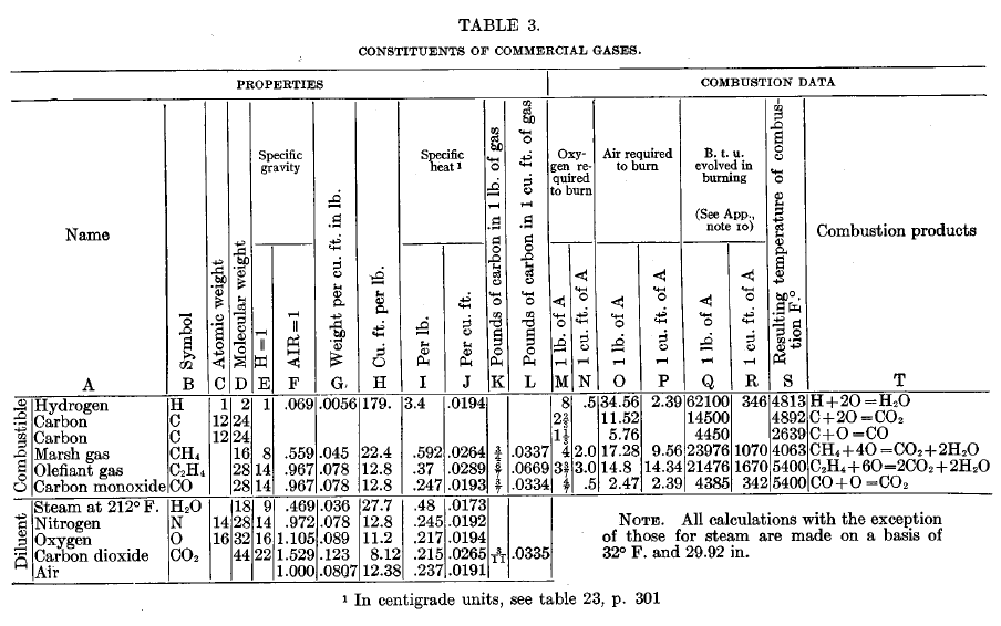
With the first four chapters written specifically for the benefit of readers who may not be familiar with the fundamental laws and definitions of physics and applied chemistry which make up the foundation of HYDROGEN-BASED ENERGY PRODUCTION, this book begins by providing YOU with the fundamental knowledge upon which any rational discussion about Hydrogen Science must be based. The first chapter acts as an excellent introduction to physical laws and definitions, covering important points such as the distinction between a vapor and a gas, Joule’s law of gases and the flow of gases. Chapter Two includes explanations of chemical laws and definitions, such as the Law of Multiple Proportion, temperature of combustion and destructive distillation. Chapter Three discusses thermal and physical calculations, including carbon-ratios and composition of gases by weight and heat carried away by products of combustion. The fourth chapter covers commercial gases, with definitions of several gases such as olefiant gas, hydrocarbons and coke-oven gas, with a comparison of commercial gases, including tabulated data. Following the four chapters of basics, Chapters 5-29 contain in-depth information about the classification manufacture utilization and efficiency of specific combustible gases as well as extensive explanations of a wide variety of “Gas-Producers.” References are cited in the text by means of their bibliographical serial numbers, and these are given in Chapter 30.
This book was written by a great man named Samuel S. Wyer. We have republished his work, "A Treatise on Producer-Gas and Gas-Producers" as, "Hydrogen Production from Organic Material by Partial Oxidation and Steam Reformation." We know you will enjoy it.
Originally titled "A Treatise on Producer-Gas and Gas-Producers," this book has been re-titled because the previous title does not mean much to people in the year 2007. Many people don't know what a "treatise" is. If you have seen the books that start with, "An Idiots Guide to...." that is basically a treatise, or a primer. It’s basically everything that you could want to know about the subject from beginning to end, with very in depth explanation. This book is extremely well written, it was written such that the average person who does not have a college education can understand it. NO instructor will be needed to interpret or explain the subject to you.
If your great grandfather (or grandfather) had an internal combustion engine to run his grain mill or small shop it probably ran on hydrogen. If he had a gas oven in his city home or apartment it ran on hydrogen. This was called a variety of names back then; Town gas, illuminating gas, water gas, producer-gas, blue gas and many others. Most of these gases were dominated by hydrogen and carbon monoxide.
Back when internal combustion engines were a new technology the refining of oil for use in an engine was not a predominate technology. Many of the first IC engines ran on gas that had to be made right next to the engine. In this sense we are calling "gas" what it is, a gas, we are not referring to the short hand for gasoline. This gas can be made from coal or coke or biomass.
Biomass can be wood, corn husks or any other type of agriculture waste (or energy crop) that can be found. The gas producers run best on 'chunky' types of fuel. Ranging in size from walnuts to softball size lumps. You can run them on smaller material and larger material but golf ball to baseball size is ideal, depending on the size of the unit being constructed.
Depending on the moisture content of your material being put in the gas producer, and whether or not you are using steam in combination with air entering the producer, the gas output of a gas producer will contain a large percentage of hydrogen (H or H2). The other dominate output product is carbon monoxide (CO). Carbon Monoxide is thought by most people to be a poison that kills people in the night when their furnace stops running correctly. Which can be true, however, CO is a beautiful fuel and burns almost as well as hydrogen does in an internal combustion engine. If additional steam
(H2O) is added to CO at the right temperature conditions, then more hydrogen (H2) is produced and the CO becomes carbon dioxide (CO2). In modern chemical language this is called a Water Gas Shift (WGS). The addition of steam or water to incandescent carbon based material to produce hydrogen (H2O + C à CO + H2) is called Stream Reformation. Adding air to a fire such that it does not have complete combustion and thus producing CO instead of the full byproduct of combustion (CO2) is called Partial Oxidation (POX). While this is a good way of making CO on a small scale the majority of this book takes this process one step further, Carbon (C) plus Oxygen (O2) from the air burning forms Carbon Dioxide (CO2). The CO2 is HOT and so is the carbon it just combusted with as is the carbon ahead of it that it is about to contact. HOT CO2 mixed with HOT C forms back down to CO. So what you get is C + O2 à CO2 + CàCO. Carbon burned with oxygen (COMBUSTINON) makes hot carbon dioxide. When this is put in contact with hot carbon it forms carbon monoxide. In this book, and in modern chemistry, this is called REDUCTION. Combustion is also called OXIDATION. So this is Oxidation / Reduction chemistry.
CHAPTER 1: FUNDAMENTAL PHYSICAL LAWS AND DEFINITIONS
Importance of laws
Forms of matter
Perfect gas
Distinction between a vapor and a gas
Vapor tension
Vapor pressure
Vapor pressure
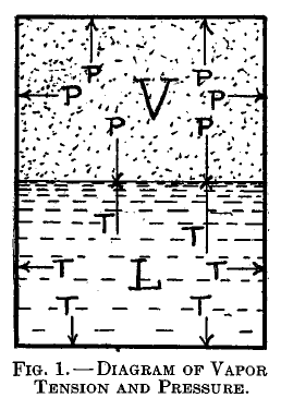
For a given liquid there corresponds to each temperature a certain definite pressure of its vapor, at which the two will remain in contact unchanged. Thus In Figure 1 the gas pressure, P, of the vapor, V, balances the vapor tension, T, of the liquid L. This gas pressure is said to be the vapor pressure of the liquid at that temperature, and the vapor itself is said to be saturated. The relation between water-vapor pressure at saturation and temperature is shown in table 11, p. 267.
Saturation
Humidity
Absolute humidity
Relative humidity
Boyle's or Mariotte's law
Law of Charles
Laws of Boyle and Charles combined
Joule's law of gases
Law of Gay-Lussac
Dalton's law
Temperature
Thermal capacity
Specific heat
Specific heat of gases
Heat unit
Density of gases
Specific volume
Specific gravity
Standard conditions
Parallel and opposite currents
Radiation
Flow of gases
Equation of pipes
CHAPTER 2: FUNDAMENTAL CHEMICAL LAWS AND DEFINITIONS
Division of matter
Atoms and molecules
Chemical affinity
Laws of thermal chemistry
Endothermic reaction
Exothermic reaction
Law of definite proportion
Law of multiple proportion
Nascent state
Oxidation
Reduction
Combustion
Temperature of combustion
Dissociation
Dissociation temperature
Heat of decomposition
Flame
Atomic and molecular weights
Destructive distillation
Fractional distillation
Direct-firing
Gas-firing
CHAPTER 3: THERMAL AND PHYSICAL CALCULATIONS
Determination of the specific heat of a mixed gas
Determination of the calorific power of a mixed gas
Carbon ratio
Calculation of volume of gas
Theoretical combustion
Weight of a mixed gas
Specific gravity of a mixed gas
Composition of gases by weight
Air required for combustion
Weight and volume of products of combustion
Heat carried away by products of combustion
Sensible heat loss of producer-gas
Flame temperature
Explosive mixtures
Calculation of moisture in air
CHAPTER 4: COMMERCIAL GASES
Definition of commercial gases
Hydrogen
Marsh gas
Olefiant gas
Carbonic oxide
Carbon dioxide
Oxygen
Nitrogen
Hydrocarbons
Water vapor
Air
Illuminants
Natural gas
Oil gas
Coal gas
Coke-oven gas
Water gas
Carbureted water gas
Comparison of commercial gases
Tabulated data
CHAPTER 5: STATUS OF PRODUCER-GAS
Progress made
Ignorance
Fuel supply
Inadaptability
CHAPTER 6: CLASSIFICATION OF GAS-PRODUCERS
Method of operation
Method of supporting fuel
Place of removing gas
Means of agitating fuel
Nature of draft
Direction of blast
Continuity of operation
CHAPTER 7: MANUFACTURE AND USE OF PRODUCER-GAS
Nature of producer-gas
Simple producef-gas
Steam-enriched gas
The action in gas-producer
Ash zone
The action in the producer
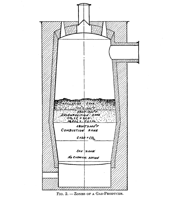
For the proper understanding of the action of a gas-producer, it is desirable to divide it into four zones, the relative position of these being given in Figure 2. However, the line of demarcation between the respective zones is not very distinct in practice.
Combustion zone
Decomposition zone
Distillation zone
Hydrocarbons
Condition of fire
Temperature of gas
Pre-heating air
Uses of producer-gas
Advantages of gas-firing
Regenerators
Recuperation
Comparison of regeneration and recuperation
Value of regeneration and recuperation
CHAPTER 8: USE OF STEAM IN GAS-PRODUCERS
Object
Action
Effect of temperature on action
Function of steam
Proportion of air and steam
Quantity of steam
Mechanical effect
Water vapor
Summary
Steam blowers
Types of steam blowers
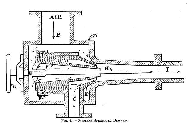
The Siemens steam-jet blower is shown in Fig. 4. It consists of a body A with air inlet B and steam inlet C. D is the outer conical nozzle and E is the inner conical nozzle. D may be adjusted by nut F and thus change the space between A and thereby regulate the amount of air that may enter. E may be adjusted by hand wheel G, and thus regulate the thickness of the annular steam jet. H is a tapering spindle to prevent reflux through the combined current. I is the pipe to the producer
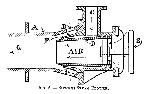
A modified form of the blower just described is shown in Fig. 5. A is the body of the blower with auxiliary air-ports B. C is the inlet for the steam which enters the mixing chamber G through the conical nozzle F. The nozzle D may be adjusted by hand wheel E. Since D is tapering, the adjusting of it will change the thickness of the annular steam jet. The air enters through B and D.
Types of steam blowers
CHAPTER 9: CARBON DIOXIDE IN PRODUCER-GAS
Presence
Effect of temperature and fuel bed
Effect of feeding
Effect of leakage
CHAPTER 10: EFFICIENCY OF GAS-PRODUCERS
Heat loss
Definition of efficiency
Two kinds of efficiency
Relation of utility and efficiency
Relation of efficiency and calorific power
Method of finding efficiency
Conditions governing efficiency
Coal and ash analysis
Grate efficiency
Heat of combustion 'of fuel
Temperatures
Figure of merit
Limited use of figure of merit
Cold-gas efficiency
Hot-gas efficiency
Effect of steam on efficiency
CHAPTER 11: HEAT BALANCE OF THE GAS-PRODUCER
Heat losses
Arrangement of heat balance
Calculation of heat balance
CHAPTER 12: FUEL
Early fuels
Character of fuel
Condition
Size of fuel
Coal
Peat
Brown coal
Refuse
CHAPTER 13: REQUIREMENTS
Adaptability
Construction of producer
Composition of gas
Automatic feeding
Continuity of operation
Agitation of fuel bed
Removal of ashes
Deep fuel bed
Introduction of blast
Cleanliness
Ease in starting
Regulation of steam and air
Heat insulation
Grate efficiency
Conservation of heat energy
CHAPTER 14: HISTORY OF GAS-PRODUCERS
Chronological record
Early use
Conservatism in improvement
Want of appreciation
Bischof producer
Bischof producer
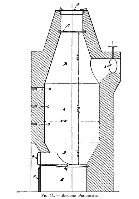
This producer is shown in Fig. 11, which gives all the general dimensions of same. The central part or body of the furnace A, where the gases are generated, is cylindrical; the upper part B and the under part D are conical. R is a grate, underneath which is an ash pit E, closed by an iron plate F. An opening immediately above the grate is arranged to be closed by an iron door G; S is a damper in the delivery flue. The throat of the producer is separated from the body by a damper C, and the top is closed by an iron lid P. The volume included between C and P is sufficient to hold one charge of the fuel with which the producer is charged at intervals; by moving C, when P is closed, the charge of fuel can be introduced through the throat without any escape of gas. The air required for combustion enters through several apertures in the plate F; these are so arranged that their areas can be increased or diminished. The progress of combustion is under control by means of the damper and the apertures referred to, and can be observed through the holes 0, which, when not in use, are closed by brick stoppers.
When the producer is working properly, its interior, as viewed through the lowest hole, should appear incandescent; at the middle hole the action should be less intense, and at the upper hole no signs of ignition should be visible. When the latter is not the case, there is much danger that the CO2 will be excessive. In order to diminish this trouble, the fuel bed should be increased in thickness and possibly the amount of air should be decreased. No blast is used and the draft is produced by the furnace which the producer supplies.
Ebelmen's producers
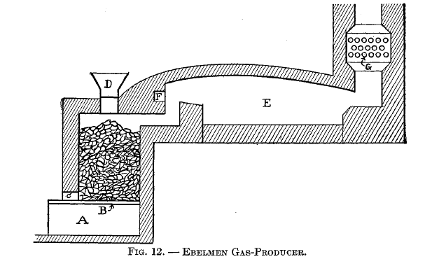
Ebelmen designed, built, and operated three types of gas-producers at the iron works of Audincourt, France. The first of these is illustrated in Fig. 12, which shows the application of the producer to a puddling furnace. A is the ash chamber into which the blast is introduced; it then passes up through the grates B and into the fuel above. Steam is admitted at C. D is the charging hopper. E is the furnace in which the gas is burned, the air for combustion being pre-heated by passing through the pipes G and then introduced into the furnace at F.
Ebelmen s producers
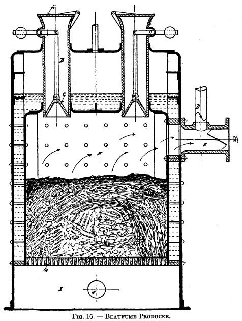 |
Beau fume producerThis producer was tried by the French Government at the Imperial Arsenal at Cherbourg, and it is shown in Fig. 16. A is the cover to the charging hopper. C is a bell which is connected to a counterweight by means of link B. E is the flue leading to the furnace and D is a pipe communicating with the atmosphere. G is the fuel bed, which is about 24 inches deep, and this is supported on the grate bars H. The blast enters the ash pit I through pipe J, then passes up through the fuel into the space F, then out into E. The entire producer is surrounded by the water jacket.
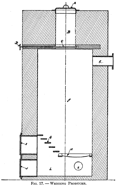
Wedding producerThis producer was in use at the Mint and Royal Porcelain Manufactory at Berlin prior to 1861. (See preface to Percy's Metallurgy, vol. on Fuel, also p. 517 therein.) It is shown in Fig. 17. A is the door to the charging chamber B. The fuel is dropped into the body of ,the producer F by means of the sliding damper C, which is operated by handle D. E is the flue leading to the furnace. G and H are grate bars. I and J are doors for gaining access to the ash-pit L. K is a pipe through which the blast enters. |
 |
Ekman producer
Beaufume producer
Wedding producer
Siemens producer
CHAPTER 15: AMERICAN PRESSURE PRODUCERS
Taylor fluxing producer
Langdon producer
Fuel gas and Electric Engineering Co.'s producer
Kitson producer
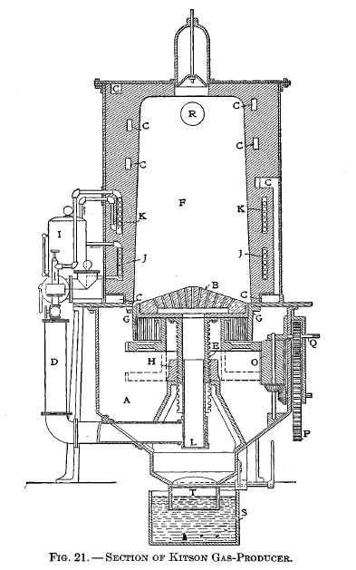
The following is an explanation of Figure 21: A ash pit, B firebrick hearth or grate, C air-passage ways for heating air supplied to injectors, D injector pipes leading to center of grate, E and H screw and hub for giving grate the rotary and up-and-down motion, F furnace, G vertical grate bars, I steam boiler, J hot-water coils connecting with boiler, K superheating steam coils communicating with boiler, L dust valve, M injectors, N hopper to supply coal to furnace, 0, P, Q mechanism for rotating grate, R gas take-off pipe, S water seal, T butterfly valve for dumping ashes.
American Furnace and Machine Co.'s producer
Amsler producer
Swindell producer
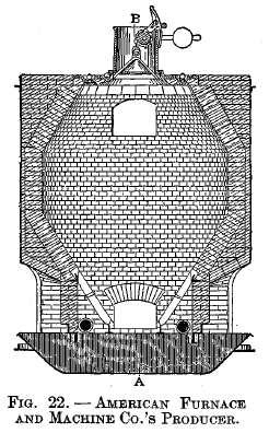
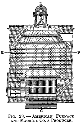
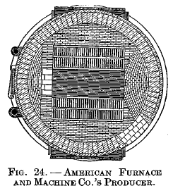
American Furnace and Machine Co.'s producer
Fig. 22 is a vertical section on line CD. Fig. 23 is a vertical section on line AB. Fig. 24 is a horizontal section on line EF. The producer consists of a cylindrical body with charging hopper above, sloping grates and water-sealed ash pit below. Two blowers are used for furnishing the blast, which is admitted under the grates as shown in Fig. 22.
Forter producer
Smythe producer
Duff producer
Taylor producer
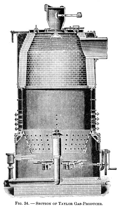 |
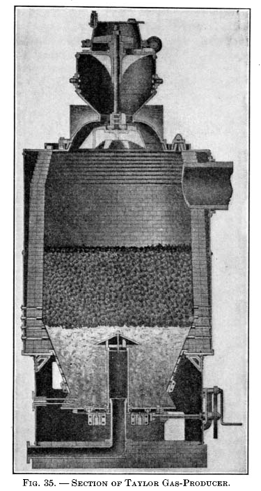
Taylor gas-producer.This producer was designed as a result of extensive experiments covering about twelve years, conducted by Mr. W. J. Taylor in connection with his ore-roasting kilns at Chester Furnace, N. J. It is shown in Fig. 34 and 35. The type illustrated in Fig. 35, with a revolving bottom and shell lined with firebrick, is that usually adopted for anthracite and a good quality of bituminous coal. For bituminous coals liable to clinker, the design with the water jacket shown in Fig. 34 is used. The clinker will not adhere so readily to the smooth sides of the water jacket as to firebrick, and the former is not liable to injury when poke bars are used from above. |
 |
Wood double-bosh producer
Wood water-seal producer
Wood flat-grate producer
Wood single-bosh water-seal producer
Wellman producer
Fraser-Talbot producer
Morgan producer
Loomis producer
Wile automatic producer
Wile water-seal producer
CHAPTER 16: AMERICAN SUCTION GAS-PRODUCERS
History of development
Definition of " suction gas-producer"
Classification
Operation
Steam supply and regulation
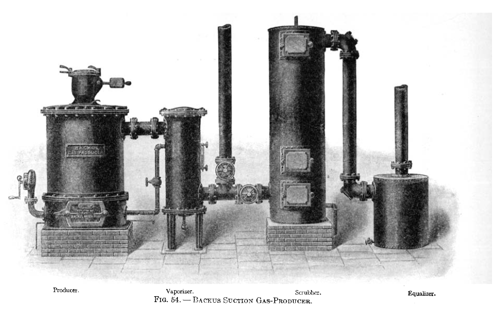
American suction producers
Nagel suction producer
Pintsch suction producer
American Crossley producer
Fairbanks-Morse suction producer
Smith suction producer
Baltimore suction producer
Wyer suction producer
CHAPTER 17: GAS-CLEANING
Object of cleaning
Classification of methods
Deflectors
Liquid scrubbers
Coolers
Absorbers or filters
Rotating scrubbers
Proportion of tower scrubbers
CHAPTER 18: BY-PRODUCT GAS-PRODUCERS
Definition
Number and value of by-products
Ammonia sulphate
Method of recovering by-products
Mond process
Mond by-product producer-gas process
This was the first process to be commercially successful and is the only one that has been introduced in this country. It was developed and perfected by Dr. Ludwig Mond of England.
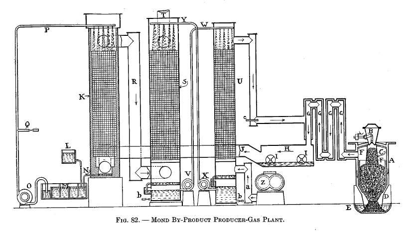
A diagrammatic drawing of a Mond plant is shown in Fig. 82. A is the producer with the charging hopper B and hopper extension C. The producer consists of two steel shells which thus form an annular space in which the air and steam may be heated by circulating around the producer. The lower end of the producer has a cone D which extends into the ash trough E, and with the water there forms a water seal. F is a thin firebrick lining. G are recuperator pipes which cool the gas and pre-heat the air and steam passing around them. H is a washer with revolving blades I. J is the pipe connecting H with ammonia-recovery tower K, which is filled with checkerwork.
L is the acid-supply tank. M is the drain tank from K, the liquor in the latter being led to M by pipe N. 0 is the liquor-circulating pump which carries the liquor to the top of K by means of pipe P. Q is a pipe leading to the concentrated ammonia sulphate tank.
R is the pipe connecting K with the gas-cooling tower S, which is filled with checkerwork. T is the gas exit; from here the gas is delivered to the mains. U is the air-heating tower, also filled with checkerwork.
V and X are pumps for circulating hot and cold water respectively, by means of pipes W and Y. Z is the air blower connected to U by pipe a. b b, tar drains. c is a pipe for admitting some of the engine exhaust gases to the air and steam blast.
The operation is as follows : As the coal is fed to C, the heat of the surrounding gases causes the moisture and some of the tarry vapors to be distilled off. In order to escape from C, these vapors must pass down and into the hot fuel bed, where they are broken up and converted into fixed gases. The fuel is kept at a dull red heat by an excessive amount of superheated steam; 3 lb. of air and 21 lb. steam at 250 degrees C. are furnished per pound of fuel. About one-sixth of the steam is decomposed in the producer, the remainder being condensed in the scrubbing apparatus. The large amount of steam is used to prevent the decomposition of the ammonia, the formation of clinkers, and to secure a low and uniform temperature.
The gas leaves the producer at about 500 degrees C., and, in passing through the recuperators G, gives up a large portion of its sensible heat to the incoming steam and air. From G the gas goes to the mechanical washer H, where the revolving dashers I fill the chamber with fine water spray which washes the dust and soot out of the gas. Tarry products will also be condensed and these may be skimmed off at intervals. In this washer the gas is cooled and charged with steam, but not to the saturation point. This is important, as it is very desirable to prevent the formation of water in the ammonia-recovery tower, which would be the inevitable result of allowing the gas to become saturated.
From H the gas goes to the tower K. The checkerwork is kept saturated with a diluted solution of sulphuric acid from the pipe P. When the ammonia in the gas comes into contact with the acid, sulphate of ammonia is formed. Thus : 2NH3 + H2SO4 = (NH4) 2SO4
Distinctive features of Mond process
CHAPTER 19: BY-PRODUCT COKE OVEN GAS-PRODUCERS
Status and future
Otto-Hoffman oven
Otto-Hoffman Oven
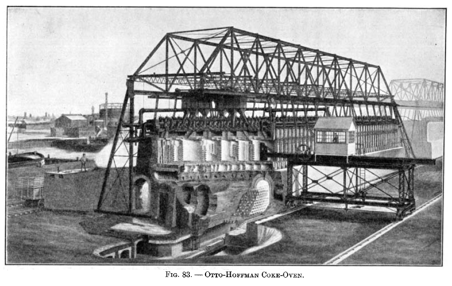
The Otto-Hoffman oven in the American form is shown in sectional perspective in Fig. 83. The coking chamber itself consists of a long, narrow retort of firebrick construction, a number of such retorts, usually 50, being placed side by side to form a battery. The dimensions of this retort are 33 ft. long, 61 ft. high, and from 17 in. to 22 in. in width, containing 6 to 7 net tons of coal at a charge. The walls of the retort are built with vertical internal flues, heated by gas. The ends of the retorts are closed by iron doors, lined with firebrick, fitting closely to the brickwork and luted with clay. These are raised and lowered by a winch or by an electrical lifting device. The coal is charged into the ovens from three larries moved by hand along tracks, laid on the oven top or, in the later plants, by a single electrically operated larry as shown in the illustration. The single larry has spouts which deliver the coal from corresponding openings in the oven top to the oven chamber below. The coke is pushed out of the oven by the electrically operated pusher and is received and quenched on a wharf, from which it is loaded by hand into railroad cars on a depressed track alongside. The heating of the oven is done by gas, returned from the condensing house through lines running along each side of the battery, there being a burner at each end of each oven. Only one burner is used at a time. The air for combustion is taken in at the end of the battery, where the gas and air reversing valves are located, and is led through the underground passages, shown in the figure, to the flues beneath the regenerative chambers. These extend the whole length of the oven battery and are filled with checker-brick. The air rising through this checkerwork is heated to a high degree, passing then through uptake connections to the space beneath the floor of the oven chambers, and through lateral ports to the combustion chamber, where it meets the gas from the burner. The burning gases rise through the vertical flues of half the wall, pass along the horizontal connecting flue above, and down the remaining vertical flues to the horizontal flues below, thence passing to the regenerator, where their sensible heat is absorbed by the checkerwork. From there they are led to the lower regenerator flue, past the reversing valve to the draft stack. On the reversal of the air and gas, the gas burner on the other end of the oven comes into use, the air passing up through the heated regenerator on that side, and to the gas chamber and combustion chamber, the heated gases passing in a reverse direction through the wall flues downward through the regenerator and so to the stack. The period of reversal is 30 minutes.
Treatment of gas
United-Otto oven
Wall construction
Heating systems
Operation
Quencher
Air and water coolers
Exhausters
Tar scrubbers
Ammonia scrubbers
Recovery of ammonia
Benzol recovery
Use of gas in engines
CHAPTER 20: PRODUCER-GAS FOR FIRING CERAMIC KILNS
Status
Value
Objections
Difficulties in using producer-gas
Heat losses
Effect of solid fuel constituents
Advantages of producer-gas
Types of producers for ceramic work
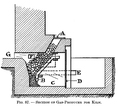 |
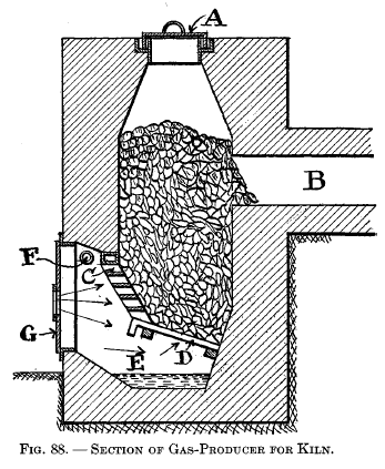
Types of gas-producers for ceramic work The producer shown in Fig. 87 is an integral part of the kiln proper. A is the charging door; B is an inclined grate over ash pit C. The air for the producer enters at D. The air required for the combustion of the gas enters at E and, in passing through the duct shown by the dotted lines, becomes pre-heated and then comes out at F and meets the hot gas from the producer, where combustion begins and is carried out into the chamber G. The producer shown in Fig. 88 is built as a separate structure from the kiln. A is the charging lid, which is kept gas-tight by means of a water seal. B is the gas flue to combustion chamber in kiln. C and D are grates, the former being so arranged that a poker may be inserted through the horizontal openings. E is the ash pit kept partially filled with water by means of pipe F, and G is the ash-pit door. |
 |
CHAPTER 21: PRODUCER-GAS FOR FIRING STEAM BOILERS
Field for use
Principle
Advantages
Requirements
Results
Methods of firing
CHAPTER 12: WOOD GAS-PRODUCERS
Field for use
Types of producers
Lundin flat-grate gas-producer
Lundin stepped-grate gas-producer
Riche distillation producer
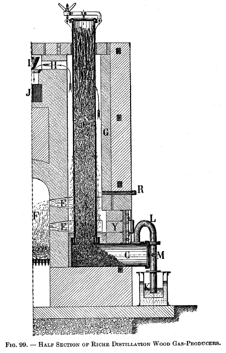 |
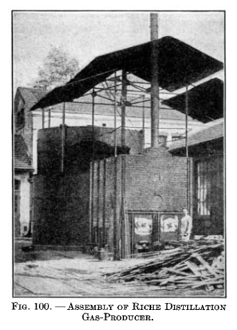
Riche distillation gas-producerThe section of this is shown in Fig. 99, while the assembly is shown in Fig. 100. The fundamental principle of the producer is to secure the destructive distillation of the wood placed in a vertical, externally heated retort. Referring to Fig. 99, the fuel to be gasified is introduced into the vertical retort denoted by A and B by means of the door placed on its top. The heating of the retort is accomplished by means of a fire in chamber F, the products of combustion passing through ports E and up around the vertical retort and out through exit ports H, valve I, and chimney flue J. The draft is regulated by the valve I. Since the combustion products first come in contact with the lower end of the vertical retort, it is evident that they will give up a large portion of their heat before they reach the exit port H. As a result, the lower end of the vertical retort will be much hotter than its upper end. R is a peep hole covered with mica, which permits the operator to observe the temperature of the vertical retort and thereupon regulate the rate of combustion by means of valve I. C is a foot chamber for the vertical retort and is connected to it by a cemented joint composed of a special refractory cement. Y is made removable so as to secure access to this joint. K is a water seal that communicates with the gas holder; the object of K is to prevent gas coming back into C when the retort is being charged with fresh fuel. M is a pipe for connecting K with the gooseneck L. |
 |
Riche double-combustion producer
CHAPTER 23: REMOVAL OF TAR FROM GAS
Object and difficulties of removal
Nature of tar
Influence. of temperature
Elimination of tar
 |
 |
 |
 |
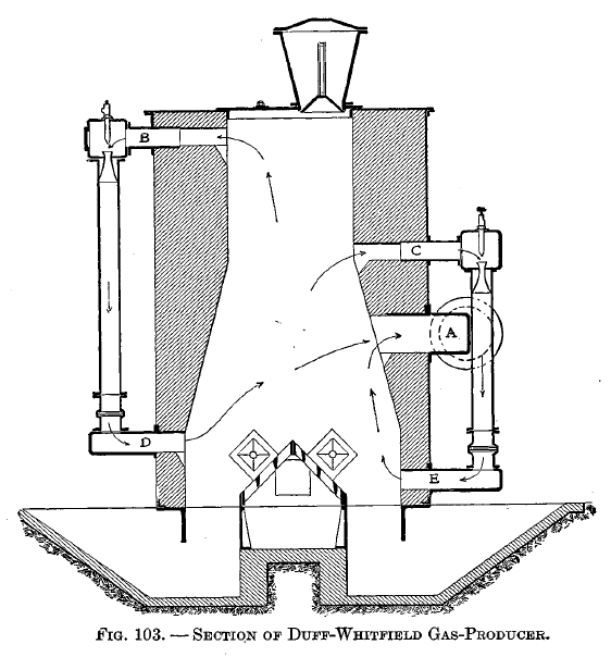
The removal of the gas in the middle of the producer and the circulation of the distillation products is illustrated in Fig. 103. A is the main gas outlet. B and C, D and E, respectively, are outlets and inlets for the distillation products.
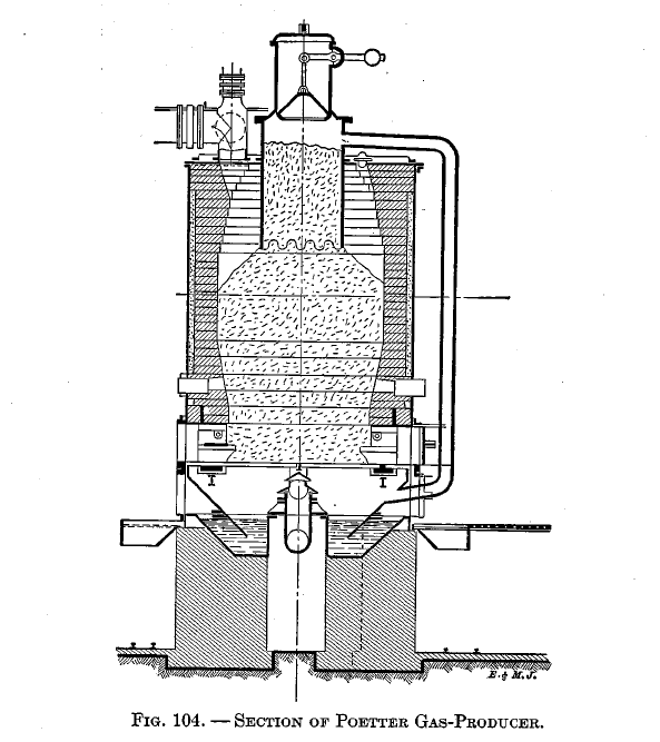
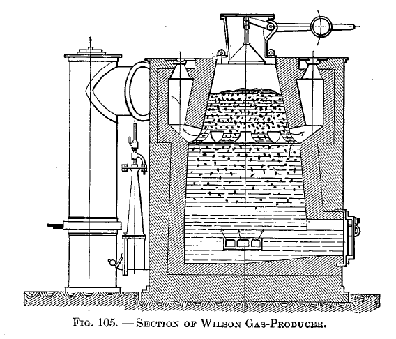
The distillation retort is shown applied to the Mond producer in Fig. 82, the Wilson producer in Fig. 105, and the Poetter producer in Fig. 104. In the Mond and Wilson producers the distillation products must pass down through the fuel; in the Poetter there is a pipe between the retort and the ash pit by means of which the distillation products may pass up through the fuel.
The passing of the gas through a separate coke chamber is illustrated in Fig. 14 and Fig. 101. The same idea is used in producers working in pairs — i.e., where the blast goes up through one fuel bed and the resulting gas down the other. The Loomis may be used in this way.
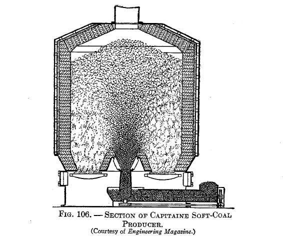
The principle of underfeeding is shown in Fig. 106, the idea being that, by introducing the fresh fuel at the bottom of the fuel bed, the resulting distillation products must pass up through the incandescent fuel.
CHAPTER 24: GAS-PRODUCER POWER PLANTS
Status
Ignorance
Newness of work
Inadaptability
Fuel economy has not been imperative
Smoke nuisance
Labor
Cost of installation
Cost of repairs
Use of cheap fuels
Scrubbing of gas
Fuel economy during hours of idleness
Time required to start producer
Time required to stop producer
Composition of gas
Thermal efficiency and economy
Automatic feeding
Rate of gasification
Poking the producer
Calorific value of producer-gas
Fuel economy
No loss from condensation
Leakage of gas
Saving in shafting
Floor space
Control of operation
Dual use of gas
Storing of heat energy
Economy of water
Driving isolated machines
Range of sizes
Danger of explosion
Location of producer plant
CHAPTER 25: OPERATION OF GAS-PRODUCERS
Erection
Starting producer
Starting engine
Stopping producer
Running producer
Cleaning of plant
Producer troubles
CHAPTER 26: TESTING GAS-PRODUCERS
Object of code
Object of test
Value of test
Determination of object
Examination of producer
General condition of producer
Character of fuel
Calibration of apparatus
Auxiliary boiler
Heating of producer
Duration of test
Starting and stopping a test
Uniformity of conditions
Keeping the records
Quantity of steam
Quality of steam
Measurement of ashes and refuse
Sampling the fuel and determining its moisture
Calorific tests and fuel analysis
Gas analysis
Calorific value of gas
Determination of water vapor, tar, and soot in gas
Report of test
CHAPTER 27: FUTURE OF THE GAS-PRODUCER
Outlook
Producer-gas locomotives
Producer-gas power plants for marine service
Producer-gas portable engines
Future development
CHAPTER 28: GAS-POISONING
Danger
Effect of carbon monoxide
Symptoms of carbon monoxide poisoning
Effect of carbon dioxide
Effect of carbon dioxide poisoning
First aid to sufferer
Artificial respiration
Post-mortem effects
CHAPTER 29: REFERENCE DATA
CHAPTER 30: BIBLIOGRAPHY
HYDROGEN PRODUCTION FROM ORGANIC MATERIAL BY PARTIAL OXIDATION AND STEAM REFORMATION $34.95
With the first four chapters written specifically for the benefit of readers who may not be familiar with the fundamental laws and definitions of physics and applied chemistry which make up the foundation of HYDROGEN-BASED ENERGY PRODUCTION, this book begins by providing YOU with the fundamental knowledge upon which any rational discussion about Hydrogen Science must be based. The first chapter acts as an excellent introduction to physical laws and definitions, covering important points such as the distinction between a vapor and a gas, Joule’s law of gases and the flow of gases. Chapter Two includes explanations of chemical laws and definitions, such as the Law of Multiple Proportion, temperature of combustion and destructive distillation. Chapter Three discusses thermal and physical calculations, including carbon-ratios and composition of gases by weight and heat carried away by products of combustion. The fourth chapter covers commercial gases, with definitions of several gases such as olefiant gas, hydrocarbons and coke-oven gas, with a comparison of commercial gases, including tabulated data. Following the four chapters of basics, Chapters 5-29 contain in-depth information about the classification manufacture utilization and efficiency of specific combustible gases as well as extensive explanations of a wide variety of “Gas-Producers.” References are cited in the text by means of their bibliographical serial numbers, and these are given in Chapter 30.
This book was written by a great man named Samuel S. Wyer. We have republished his work, "A Treatise on Producer-Gas and Gas-Producers" as, "Hydrogen Production from Organic Material by Partial Oxidation and Steam Reformation." We know you will enjoy it.

