Hydrogen Manufacture by Electrolysis, Thermal Decomposition and Unusual Techniques
 |
Hydrogen Manufacture by Electrolysis, Thermal Decomposition and Unusual Techniques
This book deals with sources and processes for the production of hydrogen. Hydrogen is often produced from natural gas and by petroleum refining. However, it is extremely important to understand and develop other means for obtaining this essential energy carrier. Hydrogen, like electricity, is not a naturally occurring energy form, but must be manufactured from basic energy resources. Again, like electricity, any basic energy resource could be used to produce hydrogen. Hydrogen Manufacture by Electrolysis, Thermal Decomposition and Unusual Techniques presents a survey of existing and future technologies for hydrogen production with an eye to their usefulness for a "hydrogen economy." Published technological studies were the basis for this review. The available material has been organized, abstracted and excerpted so as to provide YOU with a comprehensive overview of investigations and analysis of different hydrogen production practices that have been accomplished. |
The most likely long-term energy economy will utilize mixed hydrogen/electric means to carry energy to end-use. Hydrogen and electricity are the obvious technological complements because neither electricity nor hydrogen is the best choice for all applications.
Today, hydrogen is made mainly from fossil fuels. Natural gas is the primary fossil fuel source, but some is made from petroleum fractions. Petroleum refining accounts for most of this production. However, coal is the cheapest, nearest-term, large-scale source of hydrogen because coal and water are the basic chemical feed stocks needed to produce coal-derived hydrogen by well understood processes.
Nuclear power is the leading intermediate-term source of energy for hydrogen production, either by proven electrolytic means or by proposed, but unproven, thermochemical means. Both technologies require substantial improvement to compete economically with hydrogen derived from coal. Nuclear energy is also a likely long-term source of energy for hydrogen production.
Solar energy is a long-term candidate for production of hydrogen as well, either through electrolytic or thermochemical means; ultimately, solar-produced hydrogen is likely to become competitive with hydrogen derived from nuclear energy.
Most of the data in this book are based on federally funded studies. Because the information in this book is taken from many sources, it is possible that certain portions of this book may disagree or conflict with other parts of the book. This is especially true of monetary values and opinions of future potential. These different points of view, were included however, in order to make the book more valuable to the reader. Cost figures provided are those given in the cited report, the date of which is always given in the bibliography. When the dates of the cost figures are given, they are included.
The first chapter of Hydrogen Manufacture by Electrolysis, Thermal Decomposition and Unusual Techniques presents a full survey of a wide range of hydrogen technologies. The second chapter encompasses those methods which produce hydrogen from fossil fuels. Water electrolysis, as it might be used in a hydrogen economy, is covered in the third chapter, while the fourth chapter surveys proposed thermochemical means for splitting water to produce hydrogen. In the fifth chapter, more unusual sources and processes which may someday be useful in the conversion to a hydrogen economy are presented. The sixth chapter provides an overview of the economics of a hydrogen economy and the final chapter discusses various aspects of hydrogen safety. A complete bibliography of the published source material on which this book is based is also included.
The table of contents is organized in such a way as to serve as a subject index and provides easy access to the information contained in this book. Each chapter is followed by a list of references giving further details on these timely topics and the bibliography at the end of the volume lists highly important government reports.
INTRODUCTION
HYDROGEN PRODUCTION FOR THE HYDROGEN ECONOMY
Hydrogen Production from Fossil Fuels
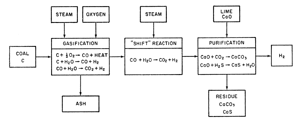
FIGURE 1.1: TYPICAL HIGH TEMPERATURE, ATMOSPHERIC PRESSURE COAL GASIFICATION PROCESS
Hydrogen from Water by Electrolysis
Closed-Cycle Thermochemical Decomposition of Water
Mixed Thermal/Electrolytic (Hybrid)
Hydrogen from Thermonuclear Fusion
Comparison of Hydrogen Production Processes
References
HYDROGEN PRODUCTION FROM FOSSIL FUELS
Production of Hydrogen by Coal Gasification
Gasification Reactions for Production of Hydrogen
Gas Producers
Gas Producers
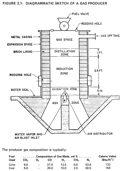
In its simplest form, a gas producer consists of a vertical brick-lined vessel on top of which is a charging hopper and on the bottom of which is a grate with the air and steam blast distributor plates. A diagrammatic sketch of a gas producer is shown in Figure 2.1 (12).
The fuel bed in the gasifier travels vertically from top to bottom, being consumed in the process of coal gasification. One can divide the bed into a succession of horizontal zones: the ash zone, the combustion (or oxidation) zone, the reduction zone, and the distillation zone.
(1) The ash zone extends from the grate upward toward a carbon combustion zone. Air and steam enter as uniformly as possible over the whole section and move upward through the bed. The air and steam cooled ash is removed by continuously rotating or intermittently moving the grate. Any clinker formed earlier is crushed. The ash is usually dropped into water-sealed troughs. For proper operation, it is most important that the blast distribution is uniform, that no gas channeling occurs, that no significant quantities of carbon remain and that the ash does not fuse.
(2) The combustion zone occupies a rather thin (about six inches thick) region in which oxygen reacts with carbon in the fuel. The temperature of this zone may reach about 3000°F. In the bottom of the zone the carbon oxidation product is primarily carbon dioxide. Near the top of this zone carbon monoxide is formed. The temperature must be closely controlled to prevent the formation of large clinker lumps, by the proper proportioning of steam and air.
(3) The reduction zone extends for a distance from one to five feet, in which the temperature drops from about 2200° to about 1500°F. Here no significant oxygen remains, most of the carbon dioxide is converted to carbon monoxide and a significant concentration of hydrogen is first noticed. Near the top of the zone no significant gasification of fixed carbon occurs.
(4) The distillation zone is a zone in which the hot gases from below preheat the coal and cause the volatilization and the cracking of the more volatile coal constituents. The character of the products of the distillation zone depends most strongly on the type of coal fed into the gasifier.
Lurgi Gasifiers
Koppers-Totzek Gasification Process
Winkler Gasification Process
Other Coal Gasification Processes
Comparison of Various Processes of Coal Gasification
Conclusions
Commercial Technology for Hydrogen Production
Catalytic Steam Reforming of Natural Gas
Partial Oxidation of Hydrocarbons
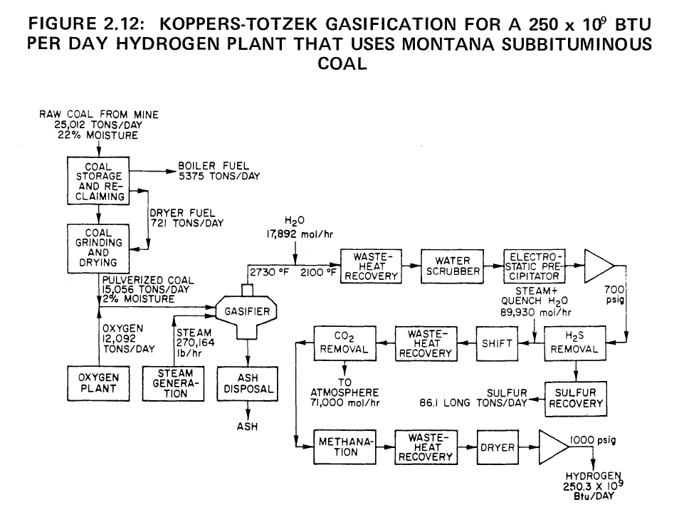
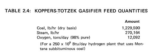
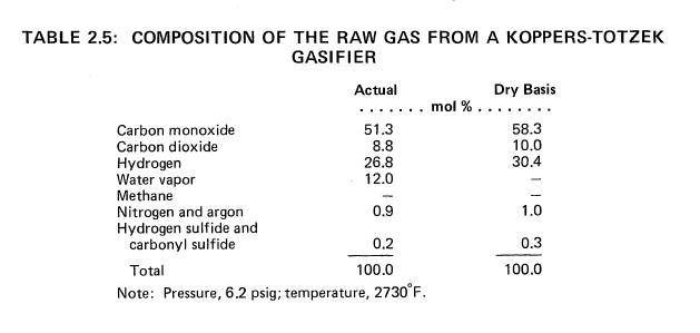
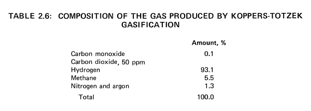
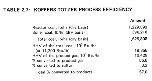
250 x 10^9 Btu of Hydrogen per Day from Montana Subbituminous Coal
By the Koppers-Totzek Process
 |
 |
 |
 |
 |
By the U-GAS Process
By the Steam-Iron Process
Use of High Temperature Nuclear Heat from an HTGR for Hydrogen Production
Hydrogen from Natural Gas
Hydrogen from Coal
By Direct Gasification of Coal with Steam
By Lurgi Gasification of Oklahoma Coal
Selection of Fossil-Based Hydrogen Production (Coal Gasification) System
Hydrogen Production from Coal Liquefaction Residues
Texaco Pilot Plant Process
References
HYDROGEN PRODUCTION BY ELECTROLYSIS
An Overview of the Technology
Principles of Electrolysis
Energy Requirements for Electrolysis
Effect of Pressure on the Decomposition Voltage
Basic Designs of Electrolyzer Cells
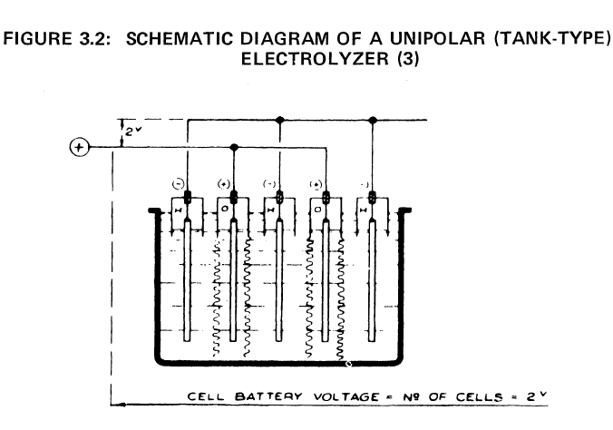 |
Basic Designs of Electrolyzer CellsThe oldest form of industrial electrolysis of water uses the tank electrolyzer in which a series of electrodes, anodes and cathodes alternately, are suspended vertically and parallel to one another in a tank partially filled with electrolyte. Alternate electrodes, usually cathodes, are surrounded by diaphragms that prevent the passage of gas from one electrode compartment to another. The diaphragm is impermeable to gas, but permeable to the cell's electrolyte. The whole assembly is hung from a series of gas collectors. A single tank-type cell usually contains a number of electrodes, and all electrodes of the same polarity are connected in parallel, electrically, as pictured in Figure 3.2. This arrangement allows an individual tank to operate across a 1.9 to 2.5 volt dc supply. In general, the cost of electrical conductors increases as the current load increases, but the cost of ac-dc rectification equipment per units of output decreases as the output voltage increases. This is one important consideration in the design of tank-type electrolyzers. There are two major advantages to tank-type electrolyzers. (1) Relatively few parts are required to build a tank-type electrolyzer, and those parts that are needed are relatively inexpensive. Because of this feature, tank-type electrolyzers tend to optimize at a lower thermal efficiency than do more sophisticated electrolyzer structures. Therefore, tank-type electrolyzers are usually selected when electric-power costs are at their lowest. (2) Individual cells may be isolated for repair or replacement simply by short-circuiting the two adjacent cells with a bus bar. This feature allows maintenance to be carried out with a minimum of downtime for the entire plant. |
Electrolyzer-System Designs
Survey of Types of Industrial Electrolyzers
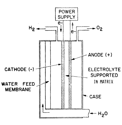 |
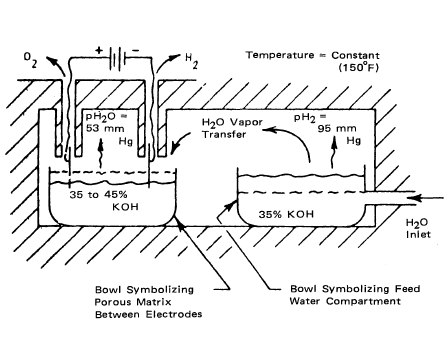
In the static water feed system, the water to be electrolyzed is supplied to the cell electrolyte as a vapor. Each cell is divided into three main compartments: a water-feed compartment, a hydrogen-gas compartment, and an oxygen-gas compartment. Compartment separation and liquid-vapor phase separation are achieved by the capillary action provided by liquid-filled asbestos sheets. Catalyzed porous-nickel plaques support the cell matrix, forming a composite electrolysis site. Plastic screens similarly support the water feed matrix. The cell configuration is given in schematic form in Figure 3.7, and Figure 3.8 shows the principle of cell operation. The latter represents a thermally insulated box enclosing two bowls of electrolyte. When power is applied to the electrodes, water in the cell electrolyte is consumed. As a result, the concentration of the cell electrolyte increases, causing its vapor pressure to drop below that of the feed-compartment electrolyte. This difference in vapor pressure is the driving force that causes the water vapor to diffuse across the hydrogen cavity to the cell matrix. |
 |
Comparative Evaluation of Various Electrolyzers
Ultimate Potential
Research and Development Requirements–Engineering Problems
Electrolyzer-Feedwater Quality Standards
Survey of Industrial Electrolyzers
Electrolyzer Corporation Ltd
Teledyne Isotopes
Lurgi Apparate-Technik GmbH
Bamag Verfahrenstechnik GmbH
Norsk Hydro Verksteder A/S
Life Systems, Inc.
General Electric
Comparison of Electrolysis Cells
Operation and Design of Large-Scale Plants
General Construction of an Electrolytic Cell
Conventional and Modified Water Electrolysis Systems for Large-Scale Production
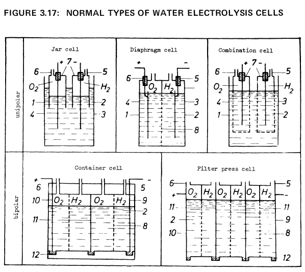
Figure 3.17 shows the schematic construction of a few cell types. Table 3.3 lists some of the technical data of typical, conventional water electrolysis methods.
1 Cell container 2 Electrolyte 3 Cathode 4 Anode 5 Hydrogen outlet 6 Oxygen outlet |
7 Gas jars 8 Diaphragm 9 Output cathode 10 Output anode 11 Bipolar electrode 12 Isolators |
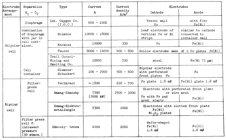
TABLE 3.3: SOME CHARACTERISTIC FIGURES FOR CONVENTIONAL WATER ELECTROLYSIS SYSTEMS
Dedicated Thermal Electric Plants
Component Characteristics
Resource Impact
Use of Heat from High-Temperature Nuclear Sources
Comparative Data on Electrolyzers
Environmental Constraints
Water Electrolysis Plants
Electrolyzer Selection
Nuclear Electrolytic Hydrogen Production Facility
Methods for Approaching Ideal Efficiencies for Hydrogen Production
Comparison of Cell Potential-Current Density Relations in Acid and Alkaline Water Electrolysis CelIs
Effect of Temperature on the Performance of Acid and Alkaline Water Electrolysis Cells
Effect of Temperature on Hydrogen and Oxygen Overpotential at Nickel Electrodes in Concentrated Potassium Hydroxide Electrolyte
Evaluation of Separator Materials to Replace Asbestos in Alkaline Solution
Conclusions
Solid Electrolyte and Elevated Temperature Water Electrolysis
General Electric Solid Polymer Electrolyte Cells
Solid Oxide Electrolyte Cells
Alkaline Water Electrolysis Cells Operating at Temperatures Between 120° a nd 150°C
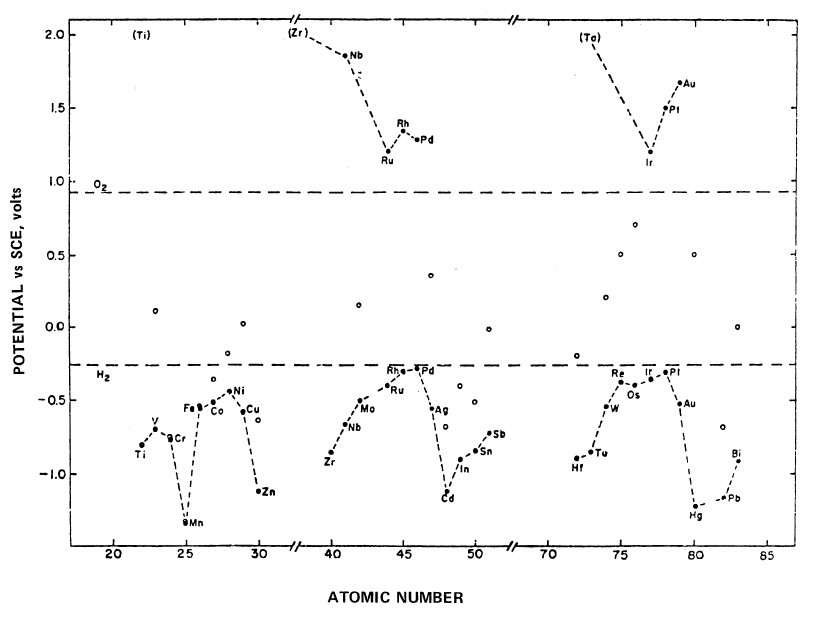
Electrocatalysis of Hydrogen and Oxygen Evolution Reactions in Alkaline Solution at 80°C: A systematic study of the electrocatalytic activities of a number of metals for the hydrogen and oxygen evolution reactions from 30% KOH at 80°C have been carried out (83). There is a periodic variation of hydrogen over-potential with atomic number (Figure 3.33). The overpotentials (at a current density of 2 mA cm-2) have minimum values for Ni, Pd and Pt which have d2s2, d10s0 and d9s1 electronic configurations respectively. High overpotentials are observed for Zn, Cd and Hg, all with d10s2 electronic configurations. The periodic trend for hydrogen overpotential shows a high correlation with the work function of the elements.
Current Status of Advanced Water Electrolysis Cells
Photoelectrochemical Effects
References
HYDROGEN PRODUCTION BY THERMOCHEMICAL PROCESSES
Water Electrolysis vs Thermochemical Production
Electrolytic Production—Off-Peak Power
Electrolytic Production—Dedicated Nuclear Plant
Thermochemical Production of Hydrogen
Hydrogen Production Co^q Computations
Sensitivity Analysis
 |
 |
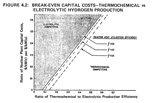
The data in Figure 4.2 assume an efficiency of one-third for the electric production efficiency and treat the efficiency of producing process heat, f, as variable, i.e., 0.5, 0.7 and 0.9. In a process heat HTGR, f can be related to the installation of intermediate heat exchanger between the reactor and the hydrogen production plant.
Based on the best information available, the ratio of capital costs for the corresponding nuclear facilities, i.e., process heat vs electric production will probably be in the range of 0.2 to 0.3. If the expected value is 0.3, the ratio of the respective production efficiencies must be 0.3 for f = 0.7. Thus, if thermochemical production of hydrogen can achieve an efficiency of 30%, it will be competitive if its capital cost is equal to the capital cost of an electrolysis plant with a projected efficiency of 90%.
In actual fact, the efficiency of electricity production may also improve to levels beyond one-third. This tends to make water electrolysis more competitive. For example, for a capital cost ratio of 0.3, the hydrogen production efficiency ratio changes from 0.33 to 0.36 for f = 0.7, when the electric production efficiency
is increased from one-third to one-half. Thus, it can be concluded that thermochemical production plants must strive to achieve practical efficiencies greater than 30% based on the expectations of current R&D on water electrolysis systems.
Estimates for processes under study suggest that theoretical efficiencies are in
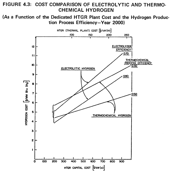
the range of 45 to 50% (6)(7)(8). Electricity generation plants are able to achieve approximately two-thirds of the theoretical Carnot efficiency. Thus, on the same basis, these processes must achieve two-thirds of the theoretical efficiency in a practical system at a capital cost equal to, but no greater than, the capital cost of a competing electrolytic production plant to be competitive. A comparison of electrolytic and thermochemical hydrogen production costs at various process efficiencies is shown in Figure 4.3.
 |
 |
Sensitivity of Capital Costs to Efficiency Variations
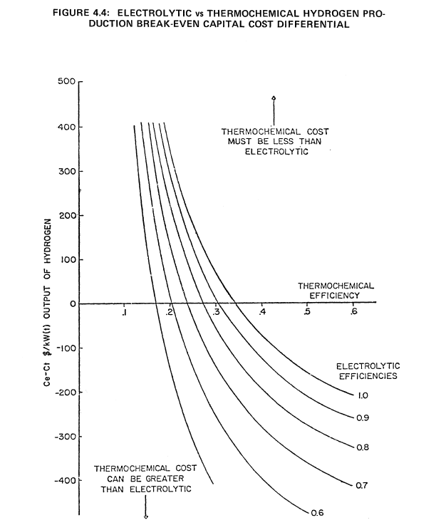
It is also possible by means of a parametric analysis to determine the allowed capital cost differential of the two types of plants as a function of the efficiency of electrolytic and thermochemical production processes. Again, it is possible to make such comparisons without specifying the absolute capital costs involved in each type of production plant. The results shown previously in Figure 4.2 were arrived at on the assumption that the capital and O&M costs of both types of plants are equal. In this case the ratio of the capital cost of a nuclear process heat plant ($/kWt) to the cost of a nuclear electric plant ($/kWe) vs the ratio of thermochemical to electrolytic production efficiency for various reactor heat utilization efficiencies was examined and cost ratio varied from 0.1 to 0.6. By choosing a fixed cost ratio of one-third and assuming a reactor heat utilization efficiency of 90% for the thermochemical process heat plant, the allowed capital cost differential between an electrolytic and thermochemical production plant, Ce-Ct, are calculated for various efficiencies of the two different production schemes. In this case, the O&M costs of both plants are assumed to be equal.
The results of this analysis are given in Figure 4.4. Ce and Ct are the respective cost of the electrolytic and thermochemical production plants in $/kWt of hydrogen output. In Figure 4.4, Ce-Ct is plotted vs the thermochemical production efficiency for various efficiency values of the electrolytic plant. Positive values of Ce-Ct correspond to the condition where the thermochemical plant capital cost must be greater than the electrolytic plant capital cost to be competitive. When Ce-Ct is negative, thermochemical plant capital cost can be greater than the corresponding cost of the electrolytic plant.
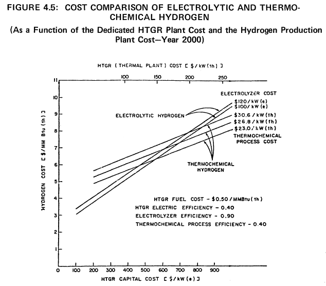
It is evident from Figure 4.4 that if the electrolytic plant production efficiency achieves 90%, the thermochemical efficiency must be at least 30% to be competitive. If the thermochemical plant achieves 40% efficiency, the capital cost can be higher than for the electrolytic plant by $75/kWt hydrogen output, i.e., the value of Ce-Ct. Using Figure 4.4 it is possible to specify various electrolytic and thermochemical efficiencies and determine the allowed capital cost differential, Ce-Ct, for the two different production schemes. A more explicit comparison of electrolytic and thermochemical hydrogen production costs, as a function of the process equipment cost is shown in Figure 4.5. These results are valid for the basic cost assumptions noted in this figure.
Off-Peak Power Costs
Break-Even Efficiency Ratio
Sensitivity of Capital Costs to Efficiency Variations
Conclusions
Survey of Thermochemical Methods
Basic Thermodynamic Considerations
Efficiency Calculations for Thermochemical Cycles
Evaluating Cycles
Heat Source Specifications and Availability
Status of the Technology
Halide Processes
Reverse Deacon Processes
Metal Processes
Ultimate Potential
Selecting A Water Decomposition Process Using Heat From High Temperature Nuclear Sources
Study of the ISPRA Mark-10 Process
Assumptions and Calculation Bases
Subsystem Functional Descriptions
Side Reactions with Potential Process Significance
Materials Availability
Environmental Constraints and Plant Effluents
Discussion of Results Assessment of Economics of Hydrogen Production from Lawrence
Livermore Laboratories ZnSe Cycle
Process Description
Key Equipment Requirements
Reference Plant
Design of an Integrated Nuclear Hydrogen Production Plant Using the Sulfur Cycle
The Westinghouse Sulfur Cycle Water Decomposition Process
Energy Sources for the Westinghouse Sulfur Cycle Water Decomposition System
References
INVESTIGATIONS OF UNUSUAL METHODS OF HYDROGEN PRODUCTION
Biophotolysis of Water
Survey of Photosynthetic Processes
Solar Energy Conversion of Water to Hydrogen Using a Ruthenium Complex
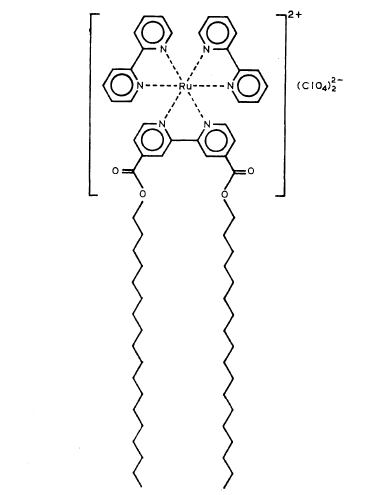
This insoluble ruthenium complex having the metal atom at the center of three bipyridyl residues and with long octadecyl tails attached to the ring has the unusual property of separating the reactive components of water to form molecular hydrogen and oxygen.
Radiolysis of Water by Dissolved Fission Products
A Survey of Other Processes
Hydrogen Production from Waste Materials
Hydrogen Production by Radiation
Direct Thermal Decomposition of Water to Produce Hydrogen
Steam-Iron System for the HYGAS Process
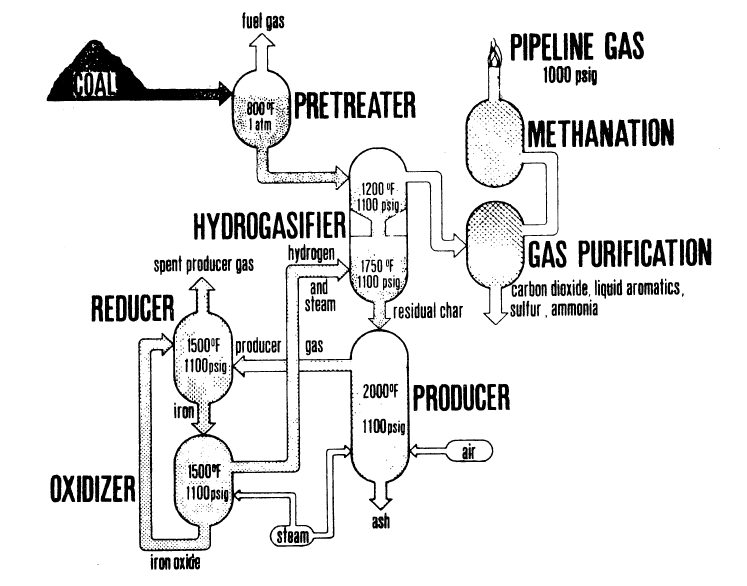
FIGURE 5.5: IGT'S HYGAS PROCESS WITH HYDROGEN GENERATION BY THE STREAM-IRON PROCESS
Figure 5.5 is a flow diagram of the steam-iron process integrated with the HYGAS process. The steam-iron system comprises three principal vessels: (1) the producer, in which residual HYGAS char is converted to reducing gases; (2) the reducer, in which iron oxide is reduced with producer gas; and (3) the oxidizer, in which the iron is reoxidized and the hydrogen is produced.
In integrated operation, spent char from the HYGAS process is fed directly to a producer vessel in which it reacts with air and steam to generate a gas capable of reducing iron oxide to iron. (In actual operation, the producer zone is contained within the hydrogasifier pressure shell.)
References
ECONOMICS OF HYDROGEN PRODUCTION
Development of Cost Estimates
Hydrogen Production Costs
Hydrogen from Coal
Hydrogen from Electrolysis of Water
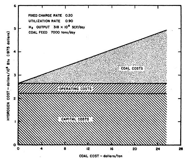
FIGURE 6.2: COST OF HYDROGEN FROM COAL AS A FUNCTION OF COAL COST
|
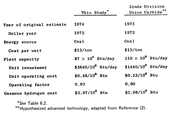
TABLE 6.4: COST ESTIMATES FOR PRODUCING HYDROGEN FROM COAL
|
Hydrogen from Thermochemical Processes
Costs of Other Fuels Compared to Hydrogen Systems
References
HYDROGEN SAFETY
Complexity of the Safety Question
Properties of Hydrogen
Hydrogen Behavior
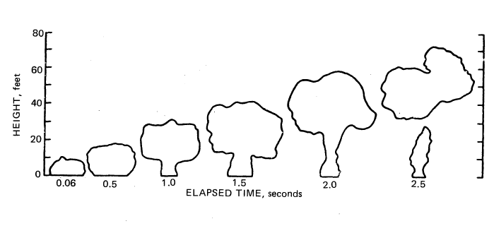
FIGURE 7.1: MAXIMUM VERTICAL CROSS SECTIONS OF FLAMES
Note that in 2 seconds the flames are nearly all dispersed upwards. Extreme care must be exercised, however, in drawing inferences from this figure about the behavior of a large spill. (A railroad tank car holds about 28,000 gallons of liquid hydrogen. This is more than 1000 times larger than the spill shown in Figure 7.1.) If liquid hydrogen were to leak from a small orifice, the effects would be less dramatic than in a large rupture spill but they would still be impressive, especially since a stream leaking from a small orifice often ignites because of static electric discharges (6).
The description above illustrates that blanket statements about hydrogen safety are inadequate because the final result of the spill depends upon the nature of the rupture, the degree of confinement, the nature of the actual nearby objects, and whether combustion is initiated. With the present state of knowledge about hydrogen and its accidents, discussions of its safety usually assume the form of "on the one hand this, but on the other hand that." Some of these kinds of discussions follow the figure.
Experience in the Space Program and the Hindenburg
Special Hazards
Summary of Physical and Chemical Aspects of Safety
Perceptions of Safety Hazards—A Key to Policy
Voluntary vs Involuntary Exposure to Hazards
References
BIBLIOGRAPHY
 |
Hydrogen Manufacture by Electrolysis, Thermal Decomposition and Unusual Techniques
This book deals with sources and processes for the production of hydrogen. Hydrogen is often produced from natural gas and by petroleum refining. However, it is extremely important to understand and develop other means for obtaining this essential energy carrier. Hydrogen, like electricity, is not a naturally occurring energy form, but must be manufactured from basic energy resources. Again, like electricity, any basic energy resource could be used to produce hydrogen. Hydrogen Manufacture by Electrolysis, Thermal Decomposition and Unusual Techniques presents a survey of existing and future technologies for hydrogen production with an eye to their usefulness for a "hydrogen economy." Published technological studies were the basis for this review. The available material has been organized, abstracted and excerpted so as to provide YOU with a comprehensive overview of investigations and analysis of different hydrogen production practices that have been accomplished. |


