Hydrogen Generator Gas for Vehicles and Engines: Volume 5
Hydrogen Generator Gas for Vehicles and Engines: Volume 5
Motor fuel is viewed by most people today as an absolute modern necessity. Without it, transport seems paralyzed, and without transport, industry cannot function. Certainly, under present conditions, cities cannot be fed and rural industries cannot be maintained without the use of motor vehicles and one does not need to be an alarmist in order to visualize a variety of circumstances which could drastically constrict the supply of oil from overseas. However, we do have a natural substitute for our imported motor fuel—at least one (probably more). The purpose of Volume 5 of the HYDROGEN GENERATOR GAS FOR VEHICLES AND ENGINES series is to set forth the possibilities of an often underestimated fossil fuel substitute: Producer Gas. This Volume, entitled, Producer Gas for Motor Vehicles, not only details Producer Gas possibilities, but also clearly explains the methods by which Producer Gas can be brought into use in a national emergency.
 |
Hydrogen Generator Gas for Vehicles and Engines: Volume 5It may be asked why producer gas has not come into general use and displaced imported fuels in times of peace. The reasons are many, but four predominate: (1) Higher first cost, (2) cumbersome equipment, (3) loss of power as compared to petrol, and (4) lack of flexibility. That producer gas running costs are lower than petrol costs is undeniable. But the easy starting of the petrol engine, its flexibility of control, the smaller amount of space required for the carriage of fuel, as well as the network of pumps whereby petrol supplies are ensured at all times and all places (in other words the selling technique of the oil companies), has kept imported motor fuels in the foreground, and producer gas has remained in the background—a scientific curiosity only. In the year 186o Lenoir invented the first successful gas engine, which operated on coal gas. This gas was expensive and required large equipment for its manufacture. The natural outcome of this was the introduction of a system whereby large quantities of gas could be made quickly, with comparatively small equipment and from low-priced fuels such as coke, charcoal, wood etc. The gas producer satisfied all of these points and so was slowly introduced. The modern gas producer is made up of three distinct elements, the efficient functioning of each being the deciding factor in the results achieved by the plant as a whole. These elements are: 1. The generator in which the fuel is burnt to produce the gas ultimately used in the engine. This is usually a cylindrical or rectangular metal container holding the fuel and into which air is admitted by means of either a grate or tuyere. 2. A scrubbing or cleaning element which removes from the gas any of the impurities it may contain. The means, of achieving this result are either dry or liquid cleaners, or in some cases a filter through which the gas is drawn. 3. A cooler or radiator. As the gas is generated from the fuel by means of a fire, the temperature of which is, very high, it will have a correspondingly high temperature which results in a loss of engine power if it is not first cooled down to a temperature of about 130° F. This is done in the cooler, or radiator as it is often called, by passing the gas through a number of pipes which are air cooled. In addition to the units just mentioned there must be some apparatus in which the producer gas and air mix to form a combustible mixture. That a gas producer is an inconvenient, bulky, and in many cases, unsightly, piece of apparatus must be admitted. But some of this prejudice must vanish when we consider the important task that it is performing. Nature itself took millions of years to produce petroleum, so it is indeed a technological feat that man, with the aid of a very simple apparatus and some wood, can produce an efficient substitute. Giant hydrogenation plants capable of producing a satisfactory substitute fuel from coal have been built at enormous cost; but the producer gas plant is the only plant that can produce a satisfactory substitute for petrol and be built within the means of any individual. This book will easily add to your general knowledge of this subject, and will help you as part of the motoring public give more thought to producer gas. Engineers, mechanics, students, experimenters and tinkerers will find the book thought provoking. |
Volume 5:
Producer Gas For Motor Vehicles
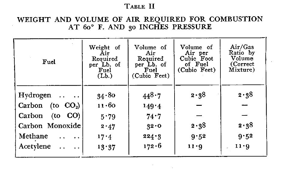
HEAT POWER AND ENERGY
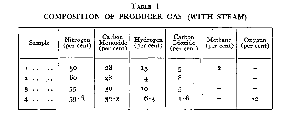
THEORY OF PRODUCER GAS
FUELS FOR GAS PRODUCERS
THE GENERATOR
UP-DRAUGHT GENERATOR
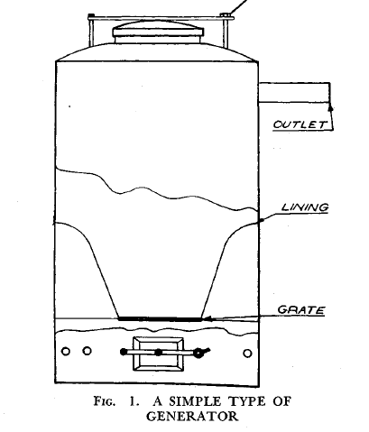
The simplest form of generator is shown in Fig. 1 and consists essentially of a cylindrical or rectangular container to which has been fitted a removable air-tight lid to permit the introduction of fuel which is burned on a grate near the bottom of the generator. A door for the removal of ash and one or more holes for the entry of air are provided below the grate. The gas outlet is placed near the top of the container and connects through the scrubbers to the engine manifold.
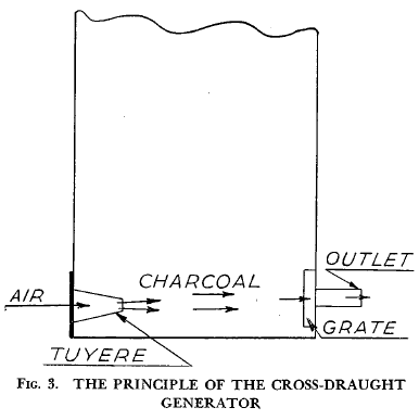 |
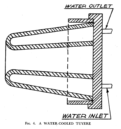
Of late years a much more suitable generator for motor vehicles has been produced which, instead of using a grate, employs what is known as a tuyere or nozzle (see Fig. 4). In this case the path of the gas through the furnace is in a horizontal direction, instead of vertically as in the previous types. This generator, of which the French plant of Gohin-Poulenc was one of the earliest examples, is known as a cross-draught type (see Fig. 3 ). |
 |
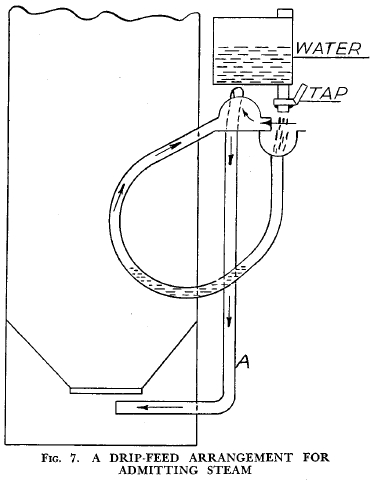 |
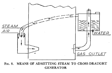
Figs 7 and 8 show two methods of admitting water. The latter cannot be so easily controlled by the operator. The apparatus shown in Fig. 7 is made up of a tank from which water drips into the mouth of a U-tube, one side of which is within the generator. In the lower sections of this tube there will be a pool of water which is being heated by the fire. Steam is given off and passes up the tube into a beehive cone, where it mixes with the incoming air and passes along the tube A, which is let into the generator below the grate. In this manner a mixture of air and steam is supplied to the fire. The system shown in Fig. 8 is an attempt at an automatic means of steam admission, the steam being produced by means of the hot gases from the generator. The advantage of this arrangement is that no steam will be admitted until the fire is hot enough to generate gases that can boil water and so give off steam, which is admitted with air to the tuyere. A more automatic arrangement could be arrived at by fitting a ball and cock valve, which would make allowance for the water boiled away. |
 |
THE SCRUBBER
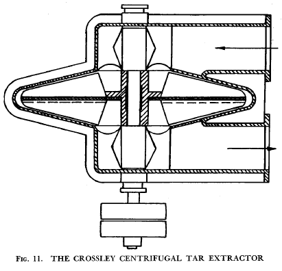 |
THE CROSSLEY CENTRIFUGAL CLEANERIn the Crossley centrifugal cleaner (see Fig. 11) the gases are directed to the centre of the fan on the inlet side and can pass to the exit only by travelling outwards on the inlet side of the casing, and back to the centre exit to the outlet pipe. Water is made to pass through the exit and, together with the separated tar, is thrown against the casing, to drain finally to the tar sump.
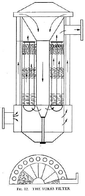
THE VOKES FILTERFig. I2 shows a filter that has been developed by Messrs Vokes Ltd in England. In this filter the gas sucked in by the engine enters a circular chamber at the bottom of the cylindrical filter case. Thence it passes upwards through a ring of tubes, much as water passes along a water-tube boiler, and so reaches the conical mouth of a large chamber. Down this chamber the gas passes, losing many of its impurities in the process, and then turns upwards once more along a series of wedge-shaped passages. In these passages are three sets of brushes looking like the ordinary bristle brushes used for cleaning flues, except that they are all on a common spindle, or rather on three spindles. |
 |
THE COOLER
FITTING GAS PRODUCERS TO MOTOR VEHICLES
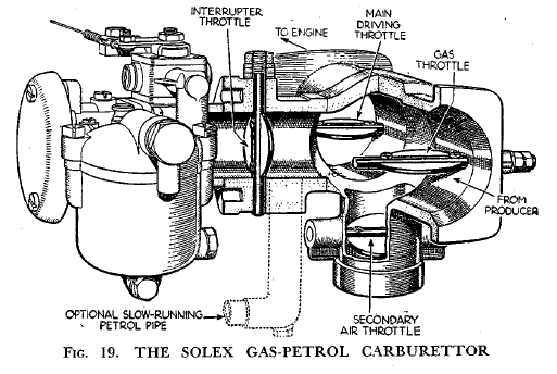
An English firm, Messrs Solex, has produced a very interesting instrument, illustrated in Fig. 19, for use when an engine is running either on petrol or on producer gas, the two separate types of fuel being available at any time.* The carburettor, as Fig. 19 shows, is made up with an extension to its body so arranged that the carburettor can be cut off entirely from this extension by an interrupter throttle. On this happening, the main throttle from the producer is opened, and thereafter the supply of mixture to the engine is controlled by a third throttle in the ordinary manner.
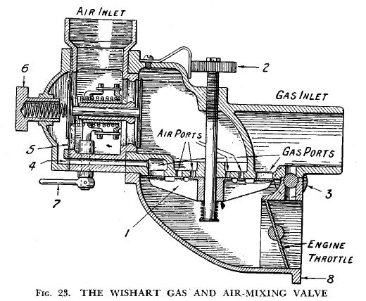
1. Triple disk valve controlling flow of gas and air.
2. Knurled adjusting screw for varying spring pressure on the disk valve.
3. Idling gas adjustment screw.
4. Gas passage to rear of diaphragm.
5. Diaphragm operating the air valve to equalize pressure of air and gas.
6. Adjustment for outer spring of diaphragm.
7. Combined diaphragm inner spring adjustment and air choke.
8. Flange for bolting to the engine inlet manifold
MEANS OF OVERCOMING POWER LOSS
DRIVING OF VEHICLES ON PRODUCER GAS
THE MAINTENANCE OF GAS PRODUCERS
FUTURE DEVELOPMENTS OF THE GAS PRODUCER
FRENCH PRODUCER GAS PLANTS
THE PANHARD GENERATOR
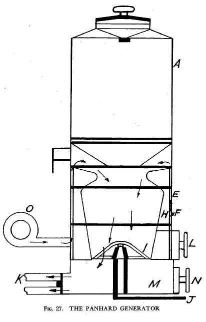
FIG. 27 shows the Panhard generator, which is of the down-draught type.
It consists essentially of a hopper (A) to which has been fitted an air-tight lid to allow of admitting the fuel. This hopper in turn is formed by an elongation of the cylindrical body (E) which is closed at the lower end by an ash hopper (M). A refractory lining (H) is provided, a steel cylinder (F) being placed outside this. The lining rests on a plate which is riveted to the cylinder. A bell-shaped grate (I) mounted on a pivot can be oscillated by means of a lever (J), thus causing the ashes to fall down into the hopper, from which they .can be removed by means of a handhole (N). A second handhole (L) gives access to the combustion chamber. The lower portion of the hopper is made in the form of a truncated cone so as to deflect the charcoal into the centre of the combustion zone. which, as previously stated, has a refractory lining. A veilleuse, or vent, is fitted to enable sufficient draught to be created to keep the fire alight when the vehicle is stopped. This vent is closed during travelling. A fan (0) is provided to light the generator.
ENGLISH PRODUCER GAS PLANTS
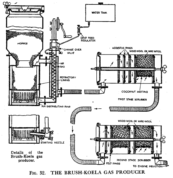
THE BRUSH-KOELA PLANT
The Brush-Koela gas producer is a plant which consists of a generator and two scrubbers; connected as shown in Fig. 32. The generator is of novel design, in as much as it incorporates both the cross-draught and up-draught principles, the former being used for starting and the latter system brought into operation for regular use. The change from one system to the other is made by a change over valve. Steam is admitted to the fire by being first vaporized by the hot exit gases. The fire grate is of the hanging basket type, and the starting tuyere is composed of carborundum in order to avoid the necessity of providing a water-cooling system which would only receive. occasional use.
AUSTRALIAN PRODUCER GAS PLANTS
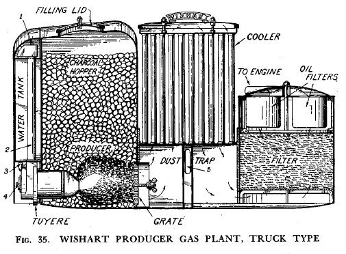
The Wishart Gas Producer is of the cross-draft type with water-cooled tuyere and a patented steam injection system which uses the steam generated in the tuyere and requires no adjustment while in operation. The section illustrated in Fig. 35 shows the truck producer, the lower portion of which forms a box frame of great strength. The essential parts—charcoal hopper, generator, steam system, water tank, dust trap, cooler, and scrubber, all of generous size—are arranged into one light-weight, compact unit to fit quickly to the front of the motor truck. In this position, it does not interfere with the cabin or loading space, and any heat generated does not come into contact with the load carried.
This producer is entirely self-regulating, and has an exceptionally long operating range. An automatic air and gas mixing valve (described elsewhere) keeps the mixture in correct proportions under all conditions, and a special idling screw is fitted. These features make the producer particularly easy to handle in traffic.
BUILDING YOUR OWN PRODUCER GAS PLANT
OPERATING COSTS OF PRODUCER GAS
APPENDIXES
INDEX
Hydrogen Generator Gas for Vehicles and Engines: Volume 5
Motor fuel is viewed by most people today as an absolute modern necessity. Without it, transport seems paralyzed, and without transport, industry cannot function. Certainly, under present conditions, cities cannot be fed and rural industries cannot be maintained without the use of motor vehicles and one does not need to be an alarmist in order to visualize a variety of circumstances which could drastically constrict the supply of oil from overseas. However, we do have a natural substitute for our imported motor fuel—at least one (probably more). The purpose of Volume 5 of the HYDROGEN GENERATOR GAS FOR VEHICLES AND ENGINES series is to set forth the possibilities of an often underestimated fossil fuel substitute: Producer Gas. This Volume, entitled, Producer Gas for Motor Vehicles, not only details Producer Gas possibilities, but also clearly explains the methods by which Producer Gas can be brought into use in a national emergency.

