Hydrogen Generator Gas For Vehicles And Engines Vol. 3&4
Hydrogen Generator Gas For Vehicles And Engines Vol. 3&4 29.95
A GASIFIER converts solid fuel to gaseous fuel. A Gasifier System includes the gasification reactor itself, along with the auxiliary equipment necessary to handle the solids, gases, and effluents going into or coming from the Gasifier.
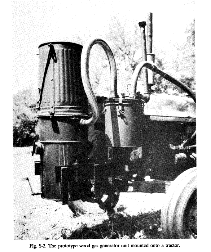
HYDROGEN GENERATOR GAS FOR VEHICLES AND ENGINES Volume 3, Construction of a Simplified Wood Gas Generator for Fueling Internal Combustion Engines in a Petroleum Emergency, is an emergency technology assessment sponsored by the Federal Emergency Management Agency (FEMA) to develop detailed, illustrated instructions for the fabrication, installation, and operation of a Biomass Gasifier which is capable of providing emergency fuel for vehicles such as tractors and trucks in the event that normal petroleum sources were severely disrupted for an extended period of time.
Volume 4, The Handbook of Biomass Gasifier Engine Systems, was initially prepared by the Solar Energy Research Institute (SERI) under the U.S. Department of Energy Solar Technical Information Program. While it was originally intended as a guide for the design, testing, operation and manufacture of small-scale (less than 200 kW) gasifiers, a great deal of the information will be extremely useful to YOU for all levels of biomass gasification. Recently, there has been expanding interest in small scale gasification around the world. We have combined these works and republished them as HYDROGEN GENERATOR GAS FOR VEHICLES AND ENGINES: Volumes 3 & 4 to help fill the continuing needs and desires for information in this fascinating field.
Hydrogen Generator Gas for Vehicles and Engines: Volumes 3 and 4
|
These Volumes present an explanation of how biomass can be converted to a gas in a Downdraft Gasifier and details for designing, testing, operating, and manufacturing Gasifiers and Gasifier Systems, as well as knowledge that was put into practical use during World War II including detailed step-by-step procedures for constructing a Producer Gas Generator for fueling internal combustion engines. HYDROGEN GENERATOR GAS FOR VEHICLES AND ENGINES: Volumes 3 & 4 also gives extensive detail on biomass fuels, gas testing and cleanup instrumentation, and safety considerations that will be extremely valuable to all those who work with Gasifiers at any scale.
The combustion of biomass in wood stoves and industrial boilers has increased dramatically in some areas, and forest, agricultural, and paper wastes are being used extensively for fuels by some industries. However, more extensive biomass use still waits for the application of improved conversion methods, such as gasification, that match biomass energy to processes currently requiring liquid and gaseous fuels. Examples of such processes include glass, lime, and brick manufacture; power generation; and transportation. Biomass, like coal, is a solid fuel and thus is inherently less convenient to use than the gaseous or liquid fuels to which we have become accustomed. An overview of various processes now in use or under evaluation for converting biomass to more conventional energy forms such as gas or liquid fuels is provided in this book. It shows how sunlight is converted to biomass through either traditional, activities (e.g., agriculture and silviculture) or via new innovative techniques that have been developed such as energy plantations, coppicing, and algaeculture. In one sense, biomass gasification is already a well proven technology. Approximately one million downdraft Gasifiers were used to operate cars, trucks, boats, trains, and electric generators in Europe during World War II, and the history of this experience is outlined in this book. However, the war's end saw this emergency measure abandoned. Development of biomass gasification was disrupted in 1946 as the war ended. and inexpensive (150/gal) gasoline became readily available. The magnitude of damage inflicted on Gasifier technology by this disruption can be seen by the fact that it was difficult for even the "advanced" technology of the 1980s to achieve .on tests what was routine operation in the 1940s. The design, research, and manufacturing teams of that decade have all disbanded. We have from the past only that small fraction of knowledge that has been published, whereas the large bulk of firsthand experience in operation design has been lost and forgotten. Gasification was rediscovered in an era of fuel shortages and higher oil prices, in its rebirth, however, the existing technology uncovered major problems in connection with effluent and gas cleanup and the fuel supply, which were less important during the emergency of World War II. Today, these problems must be solved if biomass gasification is to reemerge as a fuel source but with space-age advances in materials and control systems available for use in today's process designs, a continuous development effort and lively open exchange should enable us to incorporate latter-day chemical and chemical engineering techniques to build clean, convenient, and reliable systems. Biomass is a renewable fuel, provided that consumption does not exceed annual production. The biomass feedstock is often a low-cost byproduct of agriculture or silviculture. As such, Biomass could easily supply at least 20% of U.S. energy needs on a renewable basis. Ultimately though, the accelerated use of gasification technologies depends upon their ability to compete with fossil fuels, which in turn depends on unpredictable factors about resources, economics, and political conditions. At present, gasification and other energy processes are being developed slowly in the United States because of relatively plentiful supplies of low-cost gaseous and liquid fossil fuels. However, political changes and volatile conflicts in key oil production regions could rapidly and dramatically alter this situation, as witnessed during WWII, the OPEC oil crises of the seventies and in the aftermath of Hurricane Katrina eternally cheap oil cannot just be taken for granted. |
Volume 3:
Construction of a Simplified Wood Gas Generator for Fueling Internal Combustion Engines in a Petroleum Emergency
Abstract
Chapter 1: What is a wood Gas Generator and how does it work?
Introduction
Principles of Solid Fuel Gasification
Background Information
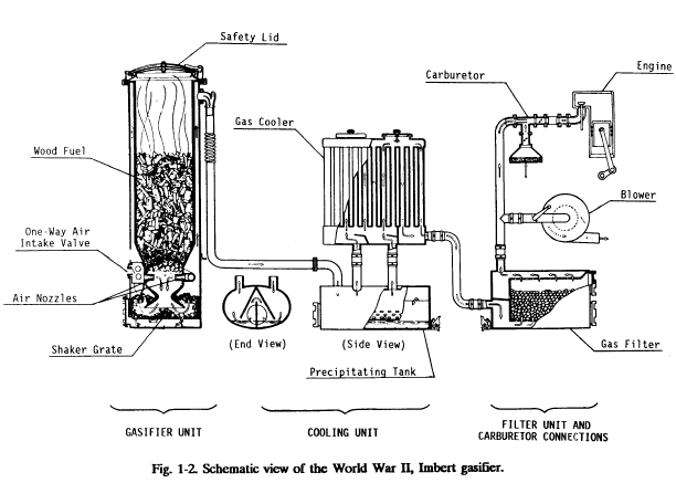
The World War II, Imbert Gasifier
The Stratified, Downdraft Gasifier
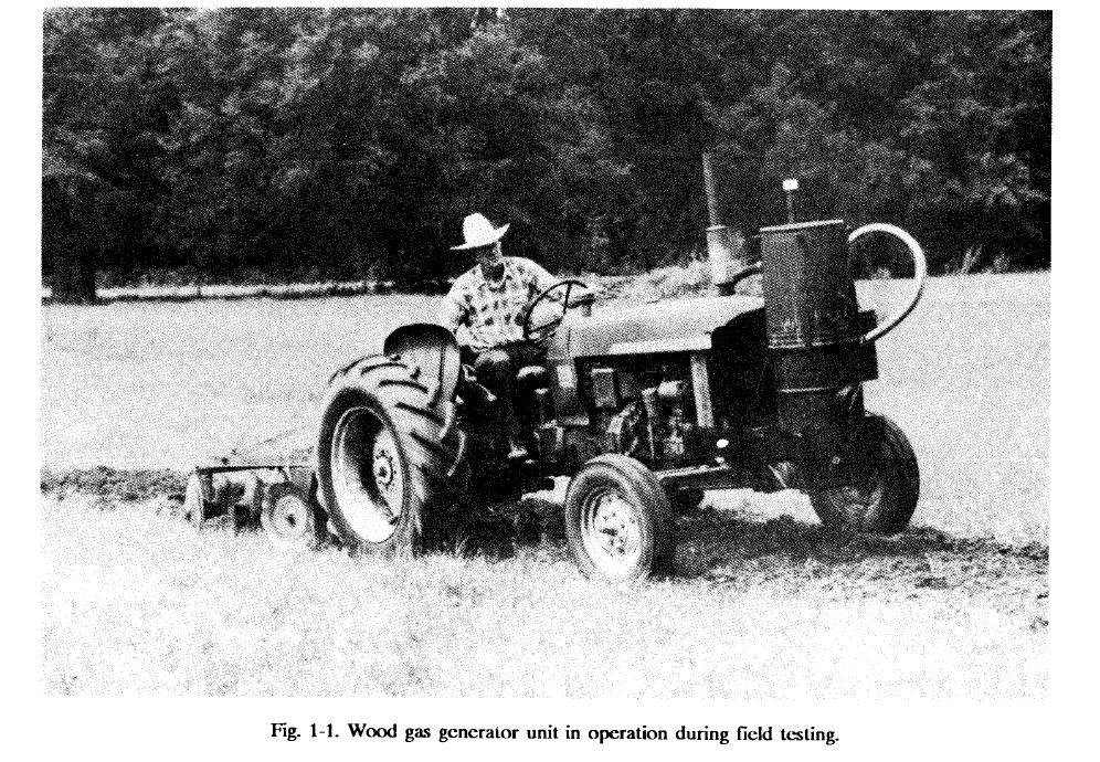
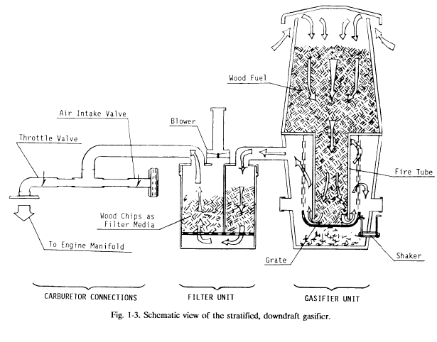
The stratified, downdraft design has a number of advantages over the WWII Imbert gasifier. The open top permits fuel to be fed more easily and allows easy access. The cylindrical shape is easy to fabricate and permits continuous flow of fuel. No special fuel shape or pretreatment is necessary; any blocky fuel can be used.
 |
 |
Chapter 2: Building Your Own Wood Gas Generator
Building The Gas Generator Unit and The Fuel Hopper
Building the Primary Filter Unit
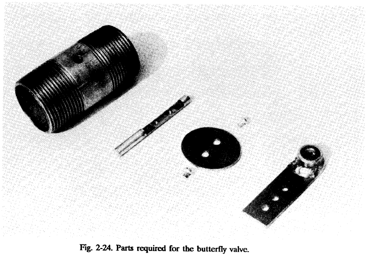
Building the Carbureting Unit With The Air and Throttle Controls
 |
 |
 |
 |
Chapter 3: Operating and Maintaining Your Wood Gas Generator
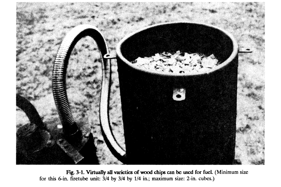
Using Wood as a Fuel
Special considerations and Engine Modifications
Initial Start-up Procedure
Routine Start-up Procedure
Driving and Normal Operation
Shutting-Down the Gasifier Unit
Routine Maintenance
Daily Maintenance
Weekly Maintenance
Biweekly Maintenance
Operating Problems and Trouble-Shooting
Hazards Associated with Gasifier Operation
Toxic Hazards
Technical Aspects of "Generator Gas Poisoning"
Fire Hazard
Bibliography
Volume 4:
HANDBOOK OF BIOMASS GASIFIER ENGINE SYSTEMS
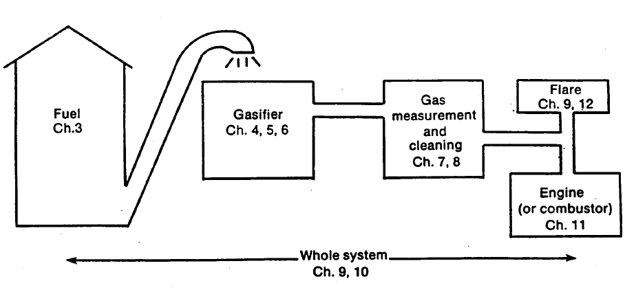
A GASIFIER converts solid fuel to gaseous fuel. A Gasifier System includes the gasification reactor itself, along with the auxiliary equipment necessary to handle the solids, gases, and effluents going into or coming from the Gasifier. The figure below shows the major components of a Gasifier System and the chapters in which they are discussed
CHAPTER 1: Introduction and Guide to the Literature and Research
Role of Gasification in Biomass Conversion
Biomass Energy Potential
Guide to Gasification Literature
Bibliographies
Books
Gasification Proceedings
Commercial Information
Producer Gas Research
Producer Gas R&D Funding
Federal Emergency Management Agency (FEMA) Gasifier Work
CHAPTER 2: History, Current Developments, and Future Directions
Historical Development
Early Development of Gasification
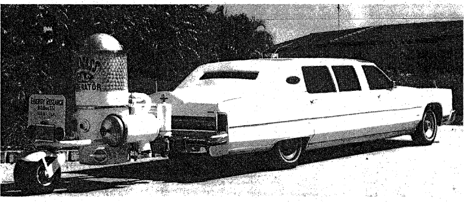
Vehicle Gasifiers
Current Development Activities

Future Development Directions
CHAPTER 3: Gasifier Fuels
Introduction
Biomass Fuel Analysis
Proximate and Ultimate Analysis
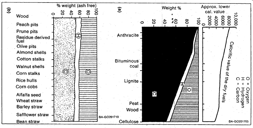
Fig. 3-1. Elemental (ultimate) analysis of (a) coals and wood and (b) biomass fuels
Physical Tests
Other Fuel Parameters
Particle Size and Shape
Charcoal and Char Properties
Biomass Ash Content and Effects
Biomass Moisture Content and Effects
Biomass Heating Value
Beneficiation of Biomass Fuels
Densifying Biomass Fuels
Drying Biomass Fuels
 |
 |
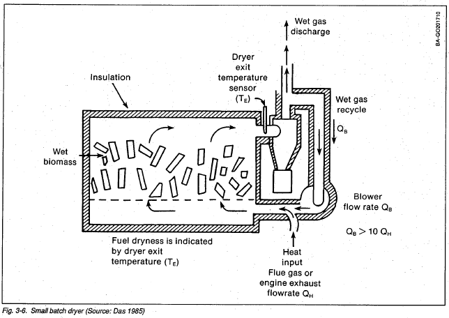
Biomass can contain more than 50% moisture (wet basis) when it is cut; it is generally desirable to dry biomass containing more than 25% moisture (wet basis) before gasification. Drying often can be accomplished using waste heat or solar energy. If the temperature of the drying air is too high, the outer surfaces of the chunk will become dry and begin to pyrolyze before the heat can reach the center. For efficient drying, hot air, which if cooled to 60°-80°C would be moisture saturated, is preferred. The moisture slows feedstock drying (as well as slowing surface pyrolysis). Thus more air is required, improving the drying process (Thompson 1981). During operation of a gasifier and engine combination, 1-in. wood chips can be dried from 50% to 5% moisture content, with drying capacity to spare, using a 20-minute residence time with the hot engine exhaust, tempered with 90% recycle of dryer gases.
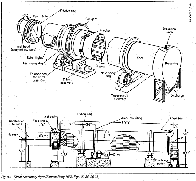
Commercial dryers are available in many forms and sizes, and it is beyond the scope of this handbook to recommend such equipment for commercial-scale operations. A simple batch dryer for drying small quantities in shown in Fig. 3-6 and a commercial dryer is shown in Fig. 3-7.
Biomass Fuel Emissions
CHAPTER 4: Principles of Gasification
Introduction
Biomass Thermal Conversion Processes
Introduction
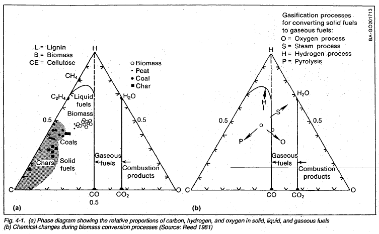
Cellulose is a linear polymer of anhydroglucose units; hemicellulose is a mixture of polymers of 5- and 6-carbon anhydrosugars, and lignin is an irregular polymer of phenyl propane units. In biomass, these three polymers form an interpenetrating system, or block copolymer, that varies in composition across the cell wall. Nevertheless, in large samples, there is a relatively *constant atomic ratio of CH1.400.6. (The ratios will vary slightly with species. Coal is typically about CH0.900.1 but varies more widely in composition.) The relationship between solid, liquid, and gaseous fuels is easily seen in Fig. 4-1(a) where the relative atomic concentrations of carbon, hydrogen, and oxygen are plotted for a variety of fuels. Here it is seen that the solid fuels, biomass, coal and charcoal, lie in the lower left segment of the diagram; liquid and gaseous hydrocarbon fuels lie in the upper left section; CO and. H2 are joined by the bisector of the triangle; and the combustion products of fuels, CO2 and H20, lie on a vertical line on the right.
Thermal conversion processes for biomass are indicated by the arrows of Fig. 4-1(b). Here it is seen that the conversion processes move the chemical composition of biomass to liquid or solid fuel regions, either by biological or thermal means. In some cases (such as oxygen/air gasification), the processes are spontaneous; in other cases (such as steam gasification) considerable energy must be expended to cause the change.
Biomass Pyrolysis
Biomass Pyrolysis
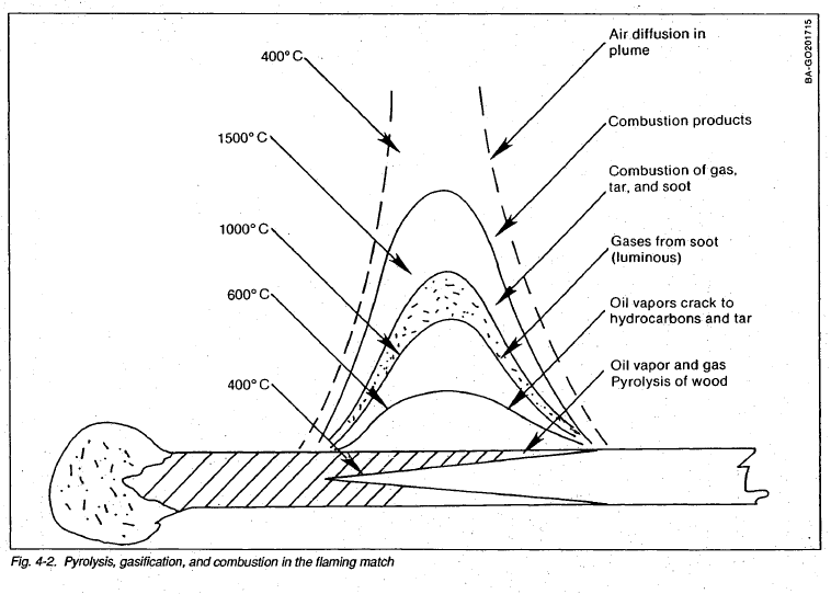
Pyrolysis is the breaking down (lysis) of a material by heat (pyro). It is the first step in the combustion or gasification of biomass. When biomass is heated in the absence of air to about 350°C (pyrolysis), it forms charcoal (chemical symbol: C), gases (CO, CO2, H2, H20, CH4), and tar vapors (with an approximate atomic makeup of CH1200.5). The tar vapors are gases at the temperature of pyrolysis but condense to form a smoke composed of fine tar droplets as they cool.
All the processes involved in pyrolysis, gasification, and combustion can be seen in the flaming match of Fig. 4-2. The flame provides heat for pyrolysis, and the resulting gases and vapors burn in the luminous flame in a process called flaming combustion. After the flame passes a given point, the char may or may not continue to burn (some matches are chemically treated to prevent the charcoal from smouldering). When the match is extinguished, the remaining wood continues to undergo residual pyrolysis, generating a visible smoke composed of the condensed tar droplets.
Combustion of Biomass
Chemistry of Biomass Gasification
Thermodynamics of Gasification
Indirect and Direct Gasification Processes
Indirect (Pyrolitic) Gasification
Direct Gasification
Principles of Operation of Direct Gasifiers
Introduction
Operation of the Updraft Gasifier
Operation of the Downdraft Gasifier
Factors Controlling Stability of Gasifier Operation
Charcoal Gasification
Summary
CHAPTER 5: Gasifier Designs
Introduction
Basic Gasifier Types
 |
 |
 |
Charcoal Gasifiers
Charcoal versus Biomass Fuels
The Crossdraft Gasifier
The Updraft Gasifier
The Imbert Downdraft Gasifier
Introduction
Description of the Downdraft (Imbert) Gasifier
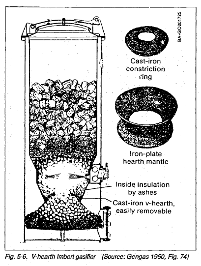 |
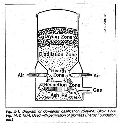
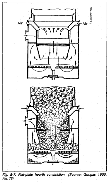
The gasifier is in many ways self-adjusting. If there is insufficient charcoal at the air nozzles, more wood is burned and pyrolyzed to make more charcoal. If too much char forms during high-load conditions, then the char level rises above the nozzles so that incoming air burns the char to reduce the char level. Thus, the reaction zone is maintained at the nozzles. Below the air nozzle zone lies the gas-reduction zone, usually consisting of a classical Imbert hearth (Fig. 5-2) or in later years, of the "V" hearth (Fig. 5-6). Most recently, the flat-plate hearth constriction (Fig. 5-7) has been introduced. The latter two hearth designs accumulate a layer of retained ash to form a high-quality, self-repairing insulation. Improved insulation in the hearth results in lower tar production and a higher efficiency over a wider range of operating conditions. |
 |
Superficial Velocity, Hearth Load, and Gasifier Sizing
Turndown Ratio
Disadvantages of the Imbert Design
The Stratified Downdraft Gasifier
Introduction
Description of the Stratified Downdraft Gasifier
Unanswered Questions About the Stratified Downdraft Gasifier
Modeling the Stratified Downdraft Gasifier
 |
 |
Modeling the Stratified Downdraft Gasifier
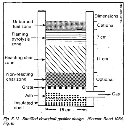
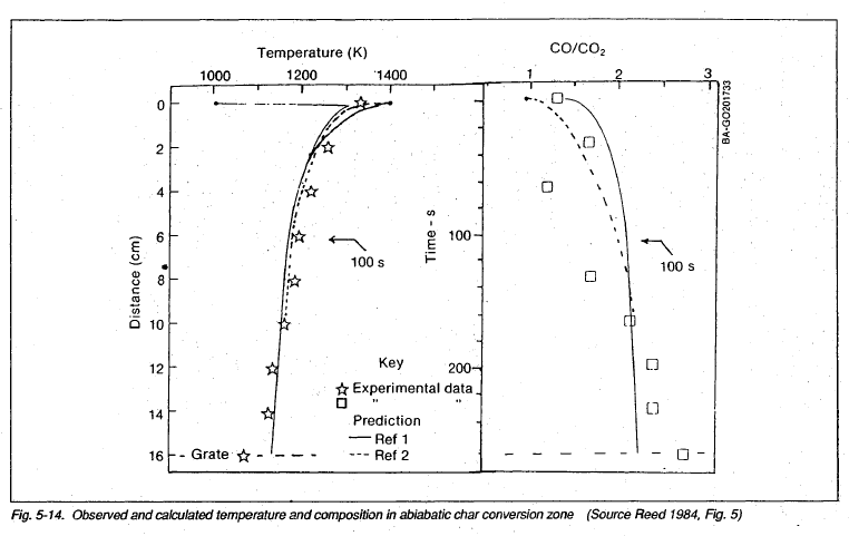
A mathematical model has been developed at SERI to predict the behavior and dimensions of the stratified downdraft gasifier (Reed 1983a, 1984, 1985a). The model is based upon predicting the length of both the flaming pyrolysis and char reaction zones from the properties of the biomass fuels and the gasifier throughput. The zone lengths predicted for various sizes of biomass fuels are given in Table 5-4, and a diagram of the gasifier, dimensioned for dry wood chips, is shown in Fig. 5-13. The predicted pyrolysis and char bed temperatures and chemical composition measured in the char bed are shown in Fig. 5-14. The interested reader is referred to the papers for further details, which are beyond the scope of this handbook.
Tar-Cracking Gasifiers
Introduction
Combustion of Tars
Thermal Tar Cracking
Catalytic Tar Cracking
Summary
CHAPTER 6: Gasifier Fabrication and Manufacture
Introduction
Materials of Construction
Methods of Construction
Sizing and Laying out the Pipes
Instruments and Controls
Temperature
Pressure
Gas Mixture
Automatic Controls
CHAPTER 7: Gas Testing
Introduction
Gas-Quality Measurements and Requirements
Description of Producer Gas and Its Contaminants
The Gas Analysis
Particulates
Tars
Gas Sampling
Sample Ports
Isokinetic Sampling
Physical Gas-Composition Testing
Raw Gas
Cleaned Gas
Chemical Gas Composition
Gas Samples for Chemical Analysis
Methods of Analysis
Water Vapor. Analysis
Analysis of Test Data
Mass Balances and Energy Balances
Flow Rate Characterization
Particle-Size.Measurement
Typical Particle-Size Distributions
Sieve Analysis
Microscopic Size Analysis
Aerodynamic Size Analysis
Graphic Analysis of Size Distribution
Physical Size Analysis
CHAPTER 8: Gas Cleaning and Conditioning
Introduction
The Power Theory of Gas Cleanup
Gas Cleanup Goals
Gas Contaminant Characteristics
Typical Dirty Gas
Gas Cleanup Goals
Cleanup Design Target
Classification of Particles
Particle Movement and Capture Mechanisms
Dry Collectors
Gravity Settling Chambers
Cyclone Separators

Cyclone Separators
Cyclones are simple and inexpensive dust and droplet separators; they are widely used on gasifiers and will be discussed in extra detail in this section.
Hot gas cyclone separators are well suited to remove solid particles larger than 10 Jim as a prefilter for the gas cooler and fine particle removal, as shown in Fig. 8-3, for a vehicle gasifier of the 1939-1945 era.
Cyclone separators are also used widely in industrial processes. The principles are well-developed, and designs are easily scaled to the necessary size. High-efficiency cyclone separators can be fabricated readily by a sheet-metal or welding shop. Cyclone design parameters are presented in this section and at greater length in Perry (1973), • Calvert (1972), and Strauss (1975). Unfortunately, the small cyclones required for small gasifiers are not available commercially, so they must be custom designed and fabricated.
Baghouse Filter
Electrostatic (Cottrell) Precipitators
Wet Scrubbers
Principles of Wet Scrubbers
Scrubber Equipment
Auxiliary Equipment
Disposal of Captured Contaminants
Char-Ash
Tar
Condensate
CHAPTER 9: Gasifier Systems
The Complete Gasifier System
Storing, Feeding, and Sealing Solids
Characteristics of Solids
Storage
Feeding Solids
Sealing Solid Flows
Fans, Blowers, Ejectors, and Compressors
Importance of Gas-Moving System Design
Fans
Blowers
Ejectors
Turbochargers and Superchargers
Flares and Product-Gas Burners
Flares
Burners
CHAPTER 10: Instrumentation and Control
The Need for Instrumentation and Control
Gasifier Instruments
Pressure Measurement
Gas Flow Measurement
Solid Flow Measurement
Temperature Measurements
Controls
Fuel-Level Controls
Pressure Controls
Temperature Controls
Computer Data Logging and Control
CHAPTER 11: Engine Adaptation and Operation
Introduction
Producer Gas for Transportation
Producer Gas for Electric Power and Irrigation
Gasifier Types Suitable for Shaft-Power Generation
Sizing the Gas Producer to the Engine
Engine Selection
Large-Vehicle Engines — Truck Engines up to 50 kW
Small Engines
Natural-Gas Engines
Diesel Engines
Cogeneration
Spark-Ignition Engine Conversion
Engine System
Gas Mixers
Power Time Lag
Engine Startup
Ignition Timing
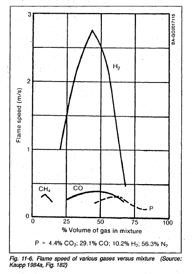 |
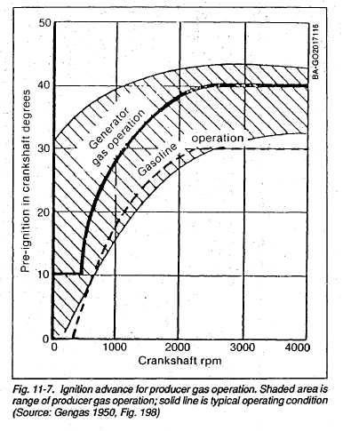
Ignition TimingProducer gas burns slowly, as shown in Fig. 11-6, giving it a high octane rating. It is usually found that optimum engine operation is obtained by advancing the ignition timing 5 to 15 degrees more than the advance used with gasoline, as shown in Fig. 11-7. The "ping-sensor" and "electronic ignition" timing controls used in many late-model automobiles may be helpful in automatically providing the ideal spark advance for producer gas, while permitting dual-fuel operation. |
 |
Spark Plugs
Two-Cycle Engine Conversion
Diesel Engine Conversion
Diesel Operation with Producer Gas
Starting Diesel Engines
Throttling at Partial Load
Increasing Power from Producer-Gas-Fueled Engines
Mechanisms of Power Loss
Engine Breathing
 |
 |
Increasing Power from Producer-Gas-Fueled Engines
Mechanisms of Power Loss
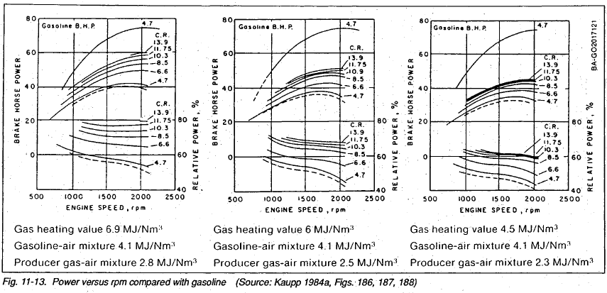
A given volume of producer gas, when mixed with the correct quantity of air for combustion, contains 70% of the energy of an equal volume of gasoline or propane mixed with air. The relative power: at any given low rpm is proportional to the mixed gas energy, as shown in Fig. 11-13. Full-throttle power increases in direct proportion to the rpm rate, up to the point where pressure drops in the intake and exhaust valves limit the power. Beyond that point, power drops off rapidly with an increasing rpm rate.
The volume of intake gases for producer gas use is roughly doubled over gasoline or propane use, and increasing pressure drops reduce the peak-power rpm by up to 30%. The combined effects of a reduced mixed-gas heating value and a reduced peak-power rpm result in an overall reduction in the maximum engine power up to 50%.
Engine Breathing
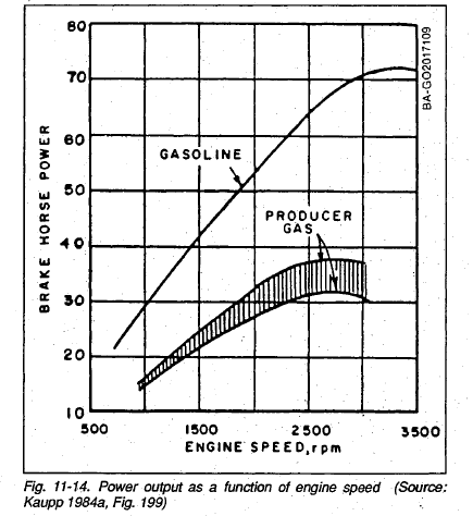
A producer gas engine must handle roughly twice the volume of intake gases as gasoline engines. The engine's breathing ability therefore begins to limit engine power at lower rpm. The peak power output, shown in Fig. 11-14, operating on producer gas, occurs at roughly two-thirds of the rpm for gasoline fuel. Improvements in the intake induction system can both raise the speed attained during the peak-power output and decrease the overall power loss at each rpm rate.
Efficiency and Power Loss
Blowers and Superchargers
Other Methods for Increasing Producer Gas Power
Engine Life and Engine Wear
Engine Life Expectancy
Sticking Intake Valves
Oil Thickening and Contamination
Tar/Oil Accumulations
Engine Corrosion
Engine Warranty
Exhaust Emissions
Other Devices for Producer-Gas Power Generation
Gas Turbines
Fuel Cells
External-Combustion Devices
CHAPTER 12: Safety and Environmental Considerations
Introduction
Toxic Hazards
Carbon Monoxide
Creosote
Fire Hazards
Environmental Hazards
CHAPTER 13: Decision Making
Introduction
Logistics Assessment
Gasifier Application
Equipment Selection Factors
Feedstock Supply
Regulations
Labor Needs
Final Logistics Considerations
Economics
Costs
Calculating Energy Costs
Equipment Cost
Conversion Efficiency and Fuel Consumption
The Cost of Operating Labor
Maintenance Costs
Cost Benefits
Value of Power Produced
Cogeneration Possibilities
Cogeneration Possibilities
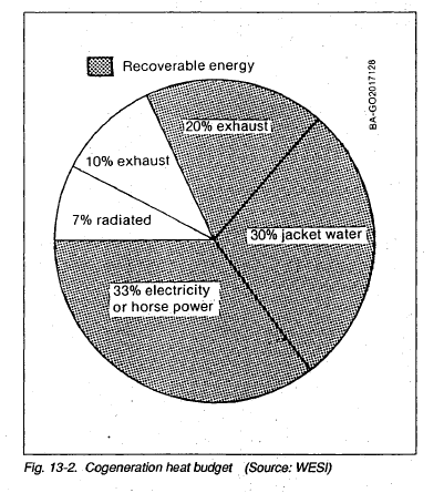
The ".waste. engine heat in the exhaust gases and engine block coolant represents from 2/3. to 3/4 of the energy supplied by the fuel. Using this waste heat from an engine (cogeneration) allows a much higher degree of energy utilization and is sometimes eligible for additional tax credits.
The size of a cogeneration system depends, of course, on the size of the heat load. Each kilowatt from an engine generator yields arund 15,000 Btfi/h in waste heat. This heat can be applied for such applications as space heating, greenhouse heating, grain drying, and absorption cycle refrigeration. Figure 13-2 indicates a heat budget for cogeneration heat recovery.
Financing
Government Subsidies in the Form of Tax Incentives
Financial Institutions
Other Considerations
References
Appendix

Hydrogen Generator Gas For Vehicles And Engines Vol. 3&4 $29.95
A GASIFIER converts solid fuel to gaseous fuel. A Gasifier System includes the gasification reactor itself, along with the auxiliary equipment necessary to handle the solids, gases, and effluents going into or coming from the Gasifier.
HYDROGEN GENERATOR GAS FOR VEHICLES AND ENGINES Volume 3, Construction of a Simplified Wood Gas Generator for Fueling Internal Combustion Engines in a Petroleum Emergency, is an emergency technology assessment sponsored by the Federal Emergency Management Agency (FEMA) to develop detailed, illustrated instructions for the fabrication, installation, and operation of a Biomass Gasifier which is capable of providing emergency fuel for vehicles such as tractors and trucks in the event that normal petroleum sources were severely disrupted for an extended period of time.
Volume 4, The Handbook of Biomass Gasifier Engine Systems, was initially prepared by the Solar Energy Research Institute (SERI) under the U.S. Department of Energy Solar Technical Information Program. While it was originally intended as a guide for the design, testing, operation and manufacture of small-scale (less than 200 kW) gasifiers, a great deal of the information will be extremely useful to YOU for all levels of biomass gasification. Recently, there has been expanding interest in small scale gasification around the world. We have combined these works and republished them as HYDROGEN GENERATOR GAS FOR VEHICLES AND ENGINES: Volumes 3 & 4 to help fill the continuing needs and desires for information in this fascinating field.


