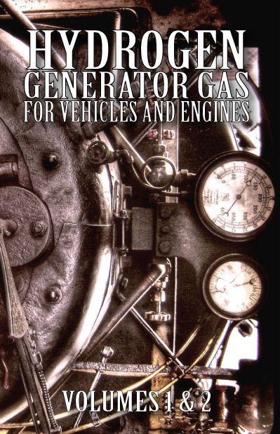
Hydrogen Generator Gas For Vehicles And Engines Vol. 1 & 2
Hydrogen Generator Gas for Vehicles and Engines: Volumes 1 and 2 $29.95
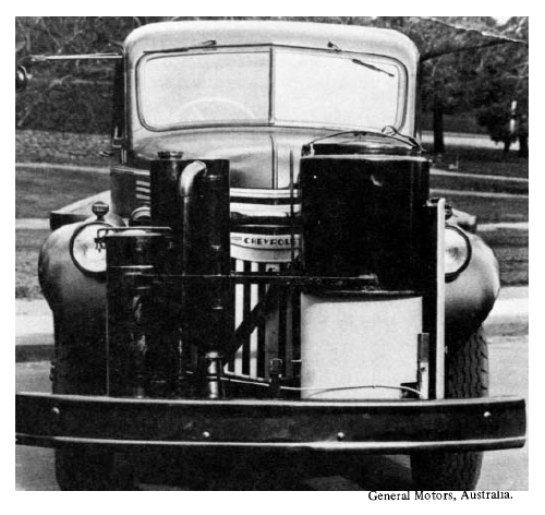
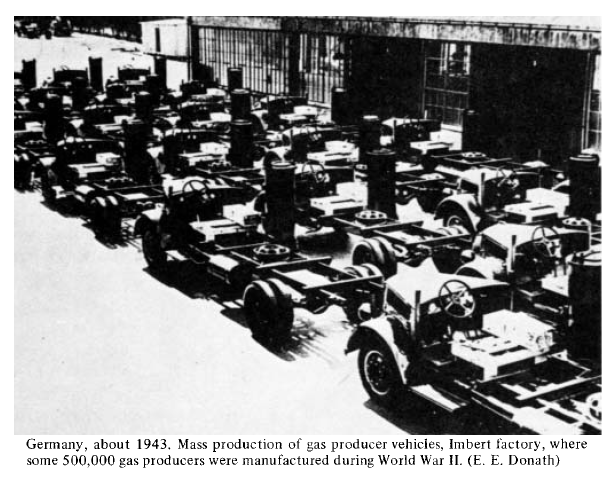
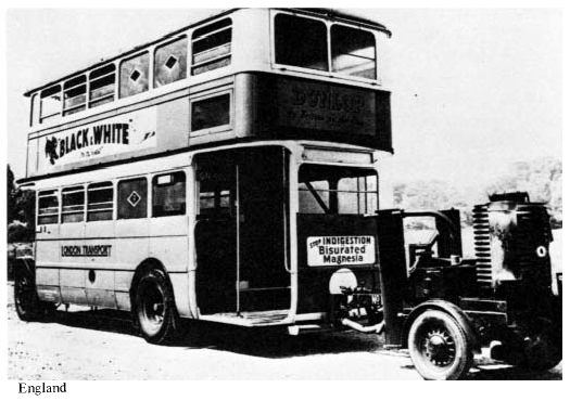
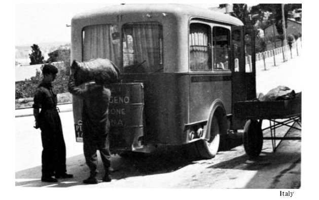
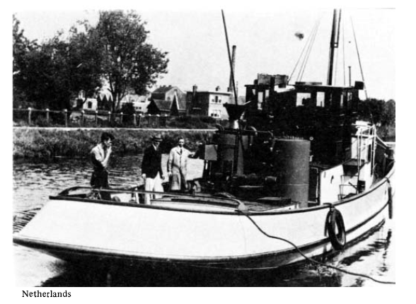
Producer gas is generated from solid fuels such as wood, charcoal, coal, peat and agricultural residues. Although it has been used to power internal combustion engines since their invention, it has been largely overlooked for the past 50 years. However, during the early 1940s, when petroleum supplies for civilian use ran out in Europe, Asia and Australia, producer gas was responsible for putting trucks, buses, taxis, tractors and other vehicles back on the roads, and boats back on the rivers. In 1938, Europe operated about 9,000 gas producer buses and trucks, and there were almost none on any other continent. By 1941, though, about 450,000 vehicles were in operation in all parts of the world, and by 1942, the number had grown to approximately 920,000. Gas producers were then in use not only in land vehicles, but also in boats, barges and stationary engines. By 1946, more than a million motorized devices around the world operated on producer gas. Although the use of producer gas in the 1940s contributed to saving millions of people from starvation in Europe and Asia alone, the world has largely forgotten all about this excellent source of energy.
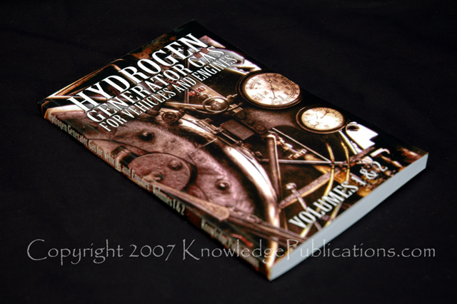
HYDROGEN GENERATOR GAS FOR VEHICLES AND ENGINES: Volumes 1 and 2 contains two great, complimentary works on the subject of Producer Gas. Each volume covers significant subject areas relevant to Producer Gas. The first volume in this book is entitled “PRODUCER GAS: ANOTHER FUEL FOR MOTOR TRANSPORT.” As the title indicates, this volume will guide you through everything you need to know about Producer Gas from its history to its economics. The second volume, “PRODUCER GAS VEHICLES” is obviously of equal importance for anyone who wishes to have a complete understanding of the true potential of Producer Gas.
 |
Fuel is essential to the economic expansion of both industrialized and undeveloped nations. Petroleum products not only run factories, trains, trucks, and buses, they also provide electricity and support production of thousands of items from foods to medicines. Internal combustion engines power police, fire fighting, ambulance, mass transit, and construction fleets, whose continued mobility is critical to the public welfare. Thus the growing demand for energy provides the incentive to investigate fuels, suited for use directly in existing vehicles without replacing the engines. The only nonpetroleum fuel now used in significant quantities in motor transport is ethanol. Research on other alternatives, such as methanol, hydrogen, liquid fuels from coal, and vegetable oil, is underway. However, Producer Gas represents a proven alternative to petroleum for fueling motor transport, although neither its practicality nor the extent of its former use is widely known. Basically, producer gas is made when a thin stream of air passes through a bed of glowing coals. The coals may come from the burning of wood, charcoal, coke, coal, peat, or from wastes such as corn cobs, peanut shells, sawdust, bagasse, and paper. (In some cases these materials must be pressed into bricks or pellets before they will produce adequate coals, and special generators also may be needed.) The gas is generated in a gasifier—a metal tank with a firebox, a grate, air inlets, and an outlet for the gas produced. On the incandescent carbon surface of the glowing coals, most of the carbon dioxide and steam, initially formed by the burning solid fuel, are reduced to carbon monoxide and hydrogen. When mixed with air, these gases are combustible. In the cylinder of a spark-ignition gasoline engine they can be ignited in the usual way with the existing spark plugs. In diesel engines, producer gas by itself will not ignite. However, diesel equipment may be operated on producer gas. The gas is mixed with the combustion air and then a small amount of diesel fuel is injected into the cylinders to provide ignition. Volume 1 of HYDROGEN GENERATOR GAS FOR VEHICLES AND ENGINES describes producer gas technology and its history, as well as the general advantages and limitations of this fuel. Volume 2 conveys general information pertaining to Producer Gas production units for road vehicles and includes descriptions of various vehicles that were actually manufactured in Australia and New Zealand. |
Contents of Book
VOLUME 1
PRODUCER GAS: ANOTHER FUEL FOR MOTOR TRANSPORT
Introduction and Conclusions
Chapter 1: History
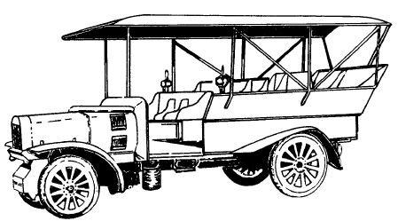 |
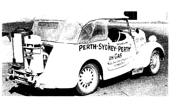
The first portable gas producer was patented by an Englishman, Samuel Brown, in 1836, but such a plant was not used for motor transport until 1901. During 1901-1903, a gas producer patented by J. W. and G. J. Parker powered first a 2.5-hp and later a 25-hp car a distance of 1,000 miles. Over the next decade, J. W. Parker made further improvements to this plant. |
 |
 |
 |
 |
 |
 |
Chapter 2: Modern Experience
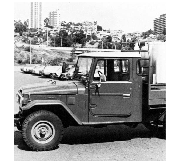
Perth, Western Australia, 1981. A Toyota diesel Land Cruiser fitted with dual firebox gas producer being tested. The unit has both an updraft generator for charcoal fuel and a downdraft generator for wood chips. The two are coupled so that gas from the wood chips passes through the burning charcoal and is purified of tars before entering the engine. For short runs, only the charcoal generator is lit. It is efficient, quick starting, and handles variable loads with little change in gas quality. For long runs, both fireboxes are lit. The gas formed by the downdraft generator supplements that from the updraft generator. The downdraft generator has three rows of air inlets (tuyeres). By unplugging the different rows a wide array of fuels and horsepowers can be accommodated. The unit shown was sized for use on an 8-ton truck.
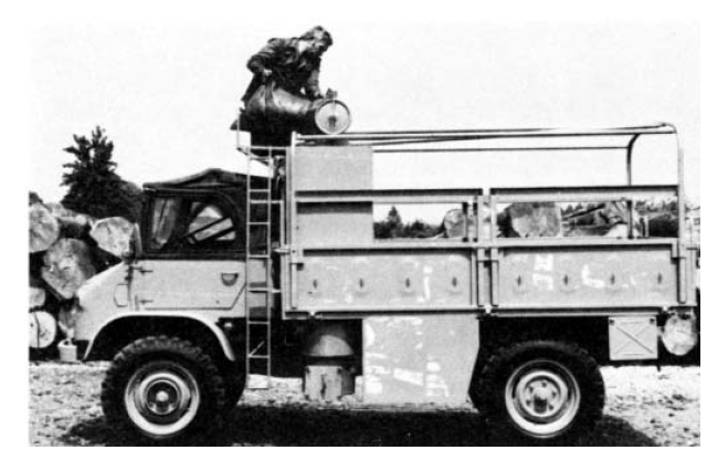
Brussels, 1979. This Mercedes Unimog recently did 100 km in 1 hour, running at full power. It used 20 kg of charcoal, with a gas producer unit weighing 450 kg, with a range of 3 hours at 60 kph. (Lambiotte, S. A., Brussels)
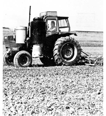 |
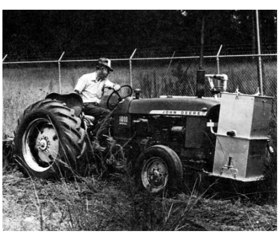
Olkkala, Finland, 1980. Wood-powered diesel tractor. (VAKOLA, Valtion Maatalouskoneiden Tukimuslaitos La Crosse, Florida, 1981. Wood-burning farm tractor used for plowing, mowing and other farm chores. |
 |
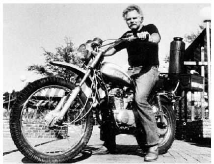 |
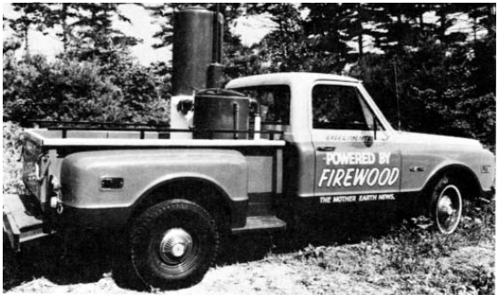
Gainesville, Florida, 1981. The tiny generator that powers this wood-burning motorcycle was constructed at the University of Florida out of a fire-extinguisher casing. The vehicle gets 70 km per kg of wood (20 miles per lb). (Sun Photo by Barbara Hansen) North Carolina, 1981. Wood-powered pickup truck sponsored by Mother Earth News. |
 |
Chapter 3: Technology
Generator
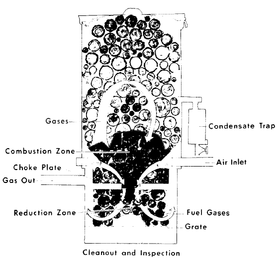
The heart of the system is the generator. It is typically a cylindrical or rectangular metal tank containing space for fuel, a firebox, and an ash pit. The upper part holds the fuel—normally a 30-minute to 2-hour supply. Its lid can be opened for refueling and is often spring-loaded to relieve any pressure that might build up inside.
The fuel falls into the combustion chamber. Air drawn through this firebox section keeps the fuel burning and produces a bed of red-hot charcoal that is at least 15 cm (6 in.) deep and is sufficiently compact that the gas streams flowing through must contact the glowing carbon surfaces. Vibration of the moving vehicle usually shakes the charcoal down and prevents "bridging.”
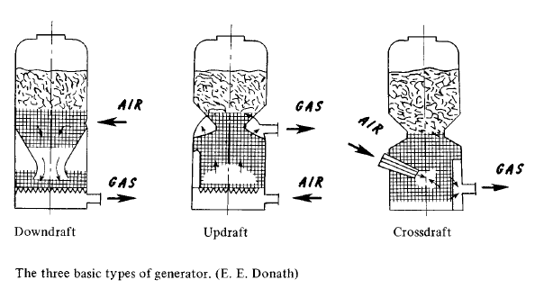
Three types of combustion chambers, differing in the relative positions of the air inlet and the gas outlet, are used.
In updraft generators, air enters below the firebox, passes upward through the incandescent charcoal, through the raw fuel in the upper section, and exits near the top of the generator. This is the simplest type of generator to build and operate. The emerging gas has practically no ash in it, but it contains tars and water vapor picked up as the gas passes upwards through the unburned fuel. Updraft generators are thus best suited for use with tar-free fuels (for example, charcoal), especially in stationary engines. They are also suitable for devices that burn gas directly to produce heat. Most town-gas generators, for example, are the updraft type.
In downdraft generators, air enters the firebox above the fire zone. Combustion gases then pass downward through the hot charcoal and exit near the bottom of the generator. This is a good type for vehicle use and for wood fuels because impurities are carried into the fire zone where tars are degraded (cracked to methane) and steam reacts to produce water gas. A constriction in the hearth (the "throat") helps ensure that all the gaseous products pass through the hottest zone. Downdraft generators produce much less tar, but more ash, in the gas than updraft generators. They are also more complicated to build and maintain.
In crossdraft generators, air enters through a nozzle projecting into the side of the firebox. The gases travel horizontally through the hot coals, exiting through the opposite side of the generator. This type of generator is suitable for motor vehicles using dry, low-tar fuels.*
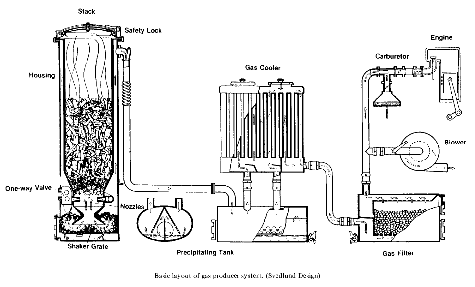
Many arrangements for introducing air to the generator have been designed. All have a one-way valve to prevent gas from exiting through the air port. Some designs cool the generator jacket with the incoming air, which also heats the air and boosts production of carbon monoxide.
The narrow air stream entering the generator causes a small zone of the fuel pile to burn very quickly and very hot (between 1,600° and 1,800° C). This generates producer gas rapidly. Air normally enters the generator through nozzles (tuyeres) that discharge it into the heart of the fuel pile. The surrounding fuel then insulates the generator walls, which can be made of mild steel rather than fire brick.
Below the throat the grate supports the burning fuel and passes the falling ash into a chamber at the bottom of the generator.
Chapter 4: Fuels
Chapter 5: Economics
Chapter 6: Stationary and Large-Scale Use
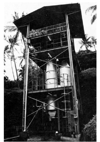
Bora Bora, French Polynesia, 1981. From 1928 to 1945 the town of Papeete, capital of Tahiti, generated the electricity needed for lighting with a gas generator fueled with coconut waste. In 1978 the island of Bora Bora (population 2,700) installed a 190-kW electricity generator fueled by gas from a stationary producer fueled by coconut shell and husks. The unit uses a small amount of diesel oil for pilot fuel. The consumption of husks is 1.5 m3, or 150 kg, per hour. This represents the husks from about 500 nuts. It is estimated that it takes 1.3 kg of husks and 50 g (or 0.06 of a liter) of diesel oil to produce 1 kWh. This means that the average consumption of electricity for each household on Bora Bora can be paid for by collecting six husks, since the price is 20.75 francs per kWh. The only real inconvenience is that the furnace must be fed every hour with 1.5 m3, or 150 kg, of husks. (Electricite de Tahiti, Papeete, photo courtesy Pacific Islands Monthly)
Chapter 7: Recommendations and Research Needs
Appendixes
A Selected Readings
B Biographical Sketches of Panel Members
Advisory Committee on Technology Innovation
Board on Science and Technology for International Development (BOSTID)
BOSTID Publications
Volume 2
PRODUCER GAS VEHICLES
PART 1: THEORETICAL DATA
THE PRINCIPAL PARTS OF PRODUCER GAS VEHICLES
PARTICULAR CHARACTERISTICS OF THE ENGINE OF A PRODUCER GAS VEHICLE
THE GAS PRODUCER DESCRIPTION AND ROLE OF ITS MAIN COMPONENTS
PART 2: PRACTICAL INSTRUCTION DRIVING AND MAINTENANCE
SETTING THE PRODUCER GAS PLANT IN ACTION
DRIVING
DAILY MAINTENANCE
MAINTENANCE AFTER 600 MIWA
DISMANTLING, ADJUSTMENT AND MINOR REPAIRS
MAKING A COVER OR INSPECTION PORT JOINT
CHECKING FOR LEAKAGE IN APPARATUS
LOCATION OF SIMPLE FAULTS
PART 3: DESCRIPTION OF PLANTS MANUFACTURED IN AUSTRALIA HIGH SPEED GAS (H.S.G.) PLANTS
OPERATION
POWELL GAS PRODUCER PLANTS
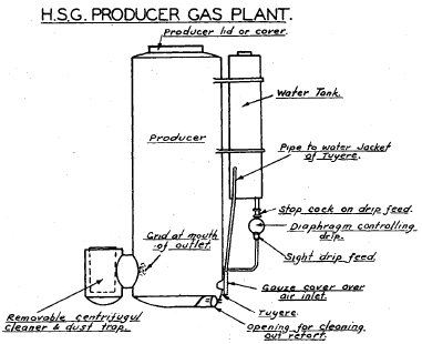 |
 |
 |
LANGE GAS PRODUCER PLANTS
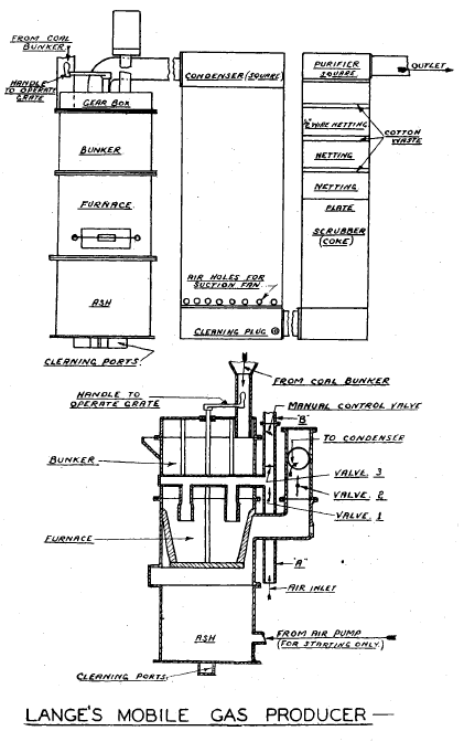
The Lange gas producer plant can burn charcoal, low quality brown coal and various briquette fuels.
The producer consists of a rectangular casing divided into three compartments. The upper compartment consists of a fuel bunker, the centre compartment forms the furnace and the lower compartment the ash pit. By means of a suitable division plate extending inside the furnace, two furnace chambers are formed, and separate air inlets are provided to each chamber.
With this producer a combination of "up" and "down" draught is obtained, and by a regulation of valves dual operation is obtained in the two separate furnace chambers. The air supply to the furnace is caused by the engine induction to produce a downflow through the furnace. Further combustion of the furnace fuel is brought about by means of an updraft created in the bottom portion of the fuel charge by means of a suitable air ejection.
In the design of the furnace when the induction action upon one chamber is caused to be alternated the full force of the updraft will act on this chamber and vice versa.
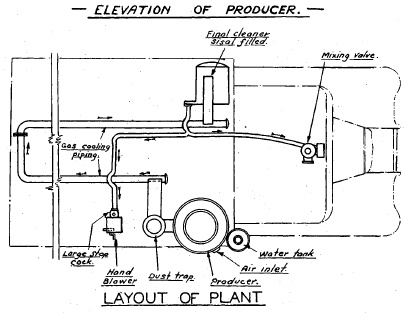
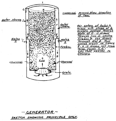
WISHART CAR TYPE GAS PRODUCER
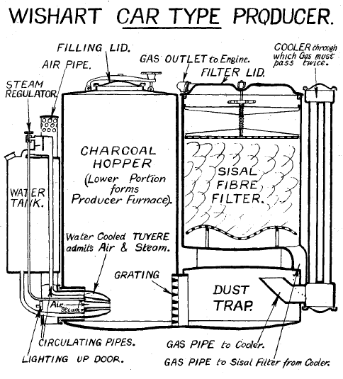
The Wishart gas producer is designed to operate on charcoal only and forms a compact and complete unit.
The plant consists of the following parts which are shown diagrammatically on the attached sketch.
1. A cylindrical producer embodying a hopper and retort. The retort or lower portion of the producer is fitted with a water cooled tuyere (or inlet nozzle) and a gas outlet or flue covered with a grid opposite the tuyere.
2. A cylindrical water tank adjacent to the hopper. This water serves a double purpose of cooling the tuyere and supplying the drip feed.
3. A dust trap, in which the greater portion of the dust contained in the gas as it leaves the producer is deposited by centrifugal action.
4. A gas cooling unit in which the temperature of the gas is reduced.
5. A final scrubber consisting of a cylindrically shaped unit filled with compressed sisal or flax which acts as a filter and extracts the finer and lighter particles of dust and prevents them entering the engine.
6. A "Mixing Valve" of special design which takes the place of the carburettor and can serve the dual purpose of a carburettor and also controls the necessary and correct proportioning of air to gas.
SMITH SUCTION GAS PLANT
INSTRUCTIONS
MAINTENANCE INSTRUCTIONS
THE GRIEG GAS PRODUCER
PART 4: DESCRIPTION OF FRENCH GAS PRODUCER PLANTS
THE GENERATOR DESCRIPTION AND NOTES ON ITS OPERATION
THE PANHARD GENERATOR (CHARCOAL)
THE BERLIET GENERATOR
THE DE DION-BOUTER GENERATOR
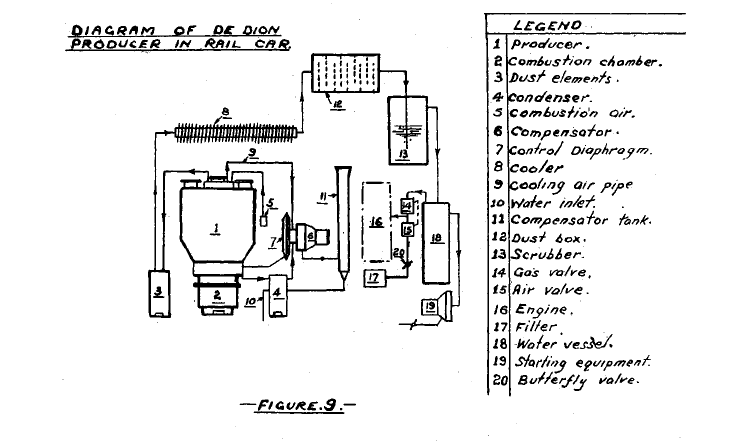
THE GOHIN-POULENC GENERATOR
THE SABATIER-DECAUVILLE
THE COOLER
THE SCRUBBER
THE INLET ORGANS
THE CONTROLS
THE FUELS USED IN GAS PRODUCER PLANTS
WOOD
CHARRED WOOD
CHARCOAL
BRIQUETTED CHARCOAL
MINERAL FUELS
PART 5: THE PRODUCTION OF CHARCOAL
BEEHIVE KILNS
BRICK KILNS
 |
 |
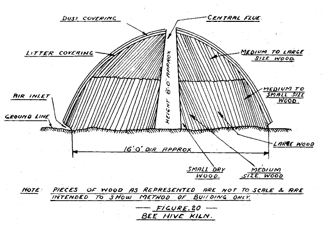
Beehive KilnsBeehive kilns are built from wood mainly 3 to 4 feet in length and each deals with up to 50 cords of wood. A chimney about one foot square cross section is first stacked from short pieces of wood in the centre of a sheltered site on light sandy soil. Around this chimney a tier of small dry wood is first stacked, then larger pieces followed by smaller pieces on the outside. One or more tiers are built above this, using larger wood for the top layer. The interstices of the stack are filled with small pieces of wood. The whole is then covered with litter and earth or dust spread over the whole hive. Air spaces are left around the base. The layout is shown diagrammatically in Figure 20. The kiln is set alight by dropping burning embers down the chimney. After three or four hours, the chimney outlet is covered with litter and earth when smoke should emerge from the whole surface of the kiln. Some experience is necessary with different timbers to get good combustion and to control it effectively. The fire burns outward from the chimney and carbonizes the wood. The kiln -gradually shrinks until, after 1i to 3 days, a kiln of the size shown in Fig. 20 occupies only about one-third of its original volume. The kiln is then cooled by several buckets full of water being poured into openings made around it. It is then tamped to make it as air tight as possible and left to cool for 12 to 16 hours. The charcoal may then be removed in small lots, but care should be taken that it does not ignite and water should be available for quenching fire. |
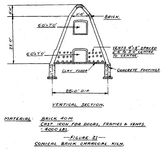
Brick KilnsBrick kilns are made in a variety of shapes, and a typical cross section of a conical design is shown in Fig. 21. They are provided with clay floors allowing drainage of tars away from the charcoal. Wood 4 ins. to 2 feet in diameter may be carbonized. About 12 days are required to complete the cycle of charging, burning, cooling and discharging.
|
METAL KILNS
GENERAL NOTES
Hydrogen Generator Gas for Vehicles and Engines: Volumes 1 and 2 $29.95
Producer gas is generated from solid fuels such as wood, charcoal, coal, peat and agricultural residues. Although it has been used to power internal combustion engines since their invention, it has been largely overlooked for the past 50 years. However, during the early 1940s, when petroleum supplies for civilian use ran out in Europe, Asia and Australia, producer gas was responsible for putting trucks, buses, taxis, tractors and other vehicles back on the roads, and boats back on the rivers. In 1938, Europe operated about 9,000 gas producer buses and trucks, and there were almost none on any other continent. By 1941, though, about 450,000 vehicles were in operation in all parts of the world, and by 1942, the number had grown to approximately 920,000. Gas producers were then in use not only in land vehicles, but also in boats, barges and stationary engines. By 1946, more than a million motorized devices around the world operated on producer gas. Although the use of producer gas in the 1940s contributed to saving millions of people from starvation in Europe and Asia alone, the world has largely forgotten all about this excellent source of energy.
HYDROGEN GENERATOR GAS FOR VEHICLES AND ENGINES: Volumes 1 and 2 contains two great, complimentary works on the subject of Producer Gas. Each volume covers significant subject areas relevant to Producer Gas. The first volume in this book is entitled “PRODUCER GAS: ANOTHER FUEL FOR MOTOR TRANSPORT.” As the title indicates, this volume will guide you through everything you need to know about Producer Gas from its history to its economics. The second volume, “PRODUCER GAS VEHICLES” is obviously of equal importance for anyone who wishes to have a complete understanding of the true potential of Producer Gas.

